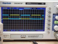
That is called 'dead time' and without it the output transistors will possibly switch on together and take out the transistors.
He's right. It's deadtime. Generally, a PS control IC limits the individual deadtime to about 49% to prevent the FETs from opposing banks from being on at the same time.
In some instances, additional deadtime is programmed into the timing for various reasons.
For regulated power supplies, the duty cycle is variable and can be from nearly 0% to about 49%.
Is this supply regulated?
Does the duty-cycle vary if you vary the 12v supply voltage?
Where were the waveforms taken from, the control IC (494?), the emitter of the drivers or the gate legs of the PS FETs?
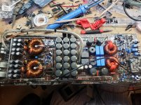
Are the rectifiers in the circuit?
In some instances, additional deadtime is programmed into the timing for various reasons.
For regulated power supplies, the duty cycle is variable and can be from nearly 0% to about 49%.
Is this supply regulated?
Does the duty-cycle vary if you vary the 12v supply voltage?
Where were the waveforms taken from, the control IC (494?), the emitter of the drivers or the gate legs of the PS FETs?
Are the rectifiers in the circuit?
How do I tell if its regulated?
The wave form was taken at the gate however it looks identical off of the ic.
The rectifiers are in
The wave form was taken at the gate however it looks identical off of the ic.
The rectifiers are in
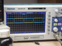
If the supply is regulated, the duty cycle will change as you vary the 12v supply voltage.
It can be normal but what you posted is excessive. For some power supplies, excessive deadtime can cause problems like creating too much ripple current in the primary filter capacitors. This can cause them to overheat and fail.
What's the DC voltage measure between pins 4 and 7 (black) on the 494?
It can be normal but what you posted is excessive. For some power supplies, excessive deadtime can cause problems like creating too much ripple current in the primary filter capacitors. This can cause them to overheat and fail.
What's the DC voltage measure between pins 4 and 7 (black) on the 494?
It's a compromise. Dead time is necessary to prevent shoot through when both mosfets are turn on simultaneously. However, depending on the mosfets and drivers too much dead time will suffer other losses in efficiency. So it's a balancing act and the designer may use the minimum dead time to avoid losses in efficiency or play it safe and sacrifice efficiency for reliability.
- Home
- General Interest
- Car Audio
- Power supply waveform help