Hello everyone,
I came across simultaneous good deals for a 1'300W Variac and a similar isolation transformer, both unboxed. Beside I was using a filament-lamp connected in serie with the phase to limit the inrush current when connecting a device in unknown condition. My bench would be a dangerous mess with all these things, so I thought let's install all of these in a big 19" metal case (recovered from some industrial devices).
In short, it has a main switch, a circuit breaker, and then a voltage/current/power measurement module (search for PZEM-021), followed by individual switch-powered outputs comprising a set of "standard" outlets, one isolated, one variable and one soft-start. All of these having a lamp to show their status. Besides the isolated output (completely floating), the metal case and all other outlets are earthed.
It would be cool if you can have a look at my schematic and provide feedback regarding the design, features, safety, etc.
Thanks !
Attachments

Great idea to put everything in one chassis.👍
It's surely make your workstation safer and cleaner.
My suggestion is to design a switch that can connect any of these devices (isolation transformer, variac and incandescent current limiter) in series.
It's surely make your workstation safer and cleaner.
My suggestion is to design a switch that can connect any of these devices (isolation transformer, variac and incandescent current limiter) in series.
Last edited:
Thanks for your suggestions, both making sense. I thought about the ability to combine the devices in series, but a switch would be complex and probably full of relays and some logic board or even micro-controller. This should stay simple and reliable, so I might go for a "manual switch", with each module being independent. Instead of the "bus", have an IEC inlet for the 3 devices, so I can wire them the way I want on the front-panel. I will need an operator then 🙂
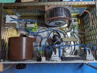
I will as well add this soft start module in front of the isolation transformer. It's a large toroid.

I will as well add this soft start module in front of the isolation transformer. It's a large toroid.
I prefer combining the Variac with the isolation Transformer. I use different solutions at different workbenches. One for repairs, with Variac and isolation transformer, and one for measurements witk 2 KVA isolation transformer for the dut and effective filtering, similar to the "Orange Audio" Filter.
Last edited:
I took over Hardi's suggestion, I can now feed the variac from the "inside bus" or from the front-panel, allowing me to feed it through the isolation transformer. A kicad schematics is more readable. Next is the front-panel design to hold all the parts. I hate mechanics CAD software but there are so many sockets and switches that I'll need a good plan.
Attachments
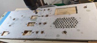
I'm making progress in the construction. Lots of holes, see attached pic. I will send other pics when done, so others may get inspiration. Meanwhile I have a question about the cabling of the isolation transformer output. Swiss sockets are well-defined, the phase "live" is right, the neutral left, the earth centered. I followed this rule for my cabling, along with the cable color that are normalized.
What I'm unsure about, is whether I should wire the earth of the isolated power output, see below the schematic part. The live and neutral will be floating, so if I wire the earth of the female socket, it will ground the housing of the powered device. In my interpretation this is desired and I'd think to cable it, but is there another way to look at this question ?

What I'm unsure about, is whether I should wire the earth of the isolated power output, see below the schematic part. The live and neutral will be floating, so if I wire the earth of the female socket, it will ground the housing of the powered device. In my interpretation this is desired and I'd think to cable it, but is there another way to look at this question ?
Attachments
It's not clear from your schematic which is the input and which is the output. Traditionally, schematics are draws such that signals flow from left to right. In a power supply, the power is the signal. That said, I'm pretty sure the Swiss T13 is an outlet, so I'm going to assume that you have the output of the circuit at the bottom of your drawing.
Here's what I'd suggest: Put a plain IEC 320-C14 on the chassis wall for the power inlet. The protective earth terminal of this INPUT goes to the chassis. The power then flows through the soft start and isolation transformer.
I would not ground the OUTPUT of the circuit. After all, the whole point of the isolation transformer is that you get the output power isolated from the input. The point of this exercise is to ensure that someone who comes into contact with either of the two conductors that carry mains voltage and building ground does not get electrocuted.
Note that this only works if you have an actual isolation transformer. I.e., one with a separate primary and secondary winding. The transformer should conform to electrical safety Class II, i.e., have reinforced insulation (double insulation) between primary and secondary.
I'm curious what the vent holes are for. Dust I/O? 🙂
Tom
Thanks Tom for your comments. Updated schematics attached, on this schema the earth of the isolated output is now unconnected.
The whole thing is a power distribution for my bench, with 4 outputs: fix, bulb-in-serie, isolation, variac. The Variac input can be the "bus" or a front-panel IEC input.
The inputs are at the top of the schematics (back of case), the outputs at the bottom, front-panel. The isolation transformer is a Triad VPT230-2170 (class B, 4'000 V). The holes in the front are to see the incandescent bulb of the 2nd circuit from the left.
Attachments
Let me make a few suggestions, this is what we did in the Monster HTPS 1000 to meet the safety requrements:
1) Use a GFCI on the output of the isolation transformer. (They go by different names in other markets than the US). It will be good protection since it trips if any current going out does not return properly. They do NOT need grounding to function.
2) The safety earth ground can be connected as long as the isolation transformer is fully isolated (two output conductors, no center tap) with no impact except for leakage current from AC Line filters. That leakage could trip the GFCI but it may be a good thing to identify marginal or failing line filters. Some EU brand line filter is notorious for the caps failing.
That's a good idea! In french we call them "disjoncteur différentiel" or "FI". I can buy a 10mA or 30mA. I think 10mA is ok, 30 mA are for garage, cellars and other humid locations. My lab is not humid, most of time 🙂
Next challenge is to find some space in the box and affix it. Updated schematics attached.
Next challenge is to find some space in the box and affix it. Updated schematics attached.
Attachments
Last edited:
I prefer combining the Variac with the isolation Transformer. I use different solutions at different workbenches. One for repairs, with Variac and isolation transformer, and one for measurements witk 2 KVA isolation transformer for the dut and effective filtering, similar to the "Orange Audio" Filter.
Excuse my ignorance but what is the Orange Audio Filter?
There should a fuse in the variac wiper ..... remenber when variac is set as a step down for voltage ... it is a step up current an output current will go too high.
You did fuse the input at 6 amp but if variac is set to lower the voltage by 4 .... output current can reach 24 amp ... this a bad condition.
If the variac is build for 5 amp it is the wiper current that must be limited to 5 amp... so fuse the wiper!
You did fuse the input at 6 amp but if variac is set to lower the voltage by 4 .... output current can reach 24 amp ... this a bad condition.
If the variac is build for 5 amp it is the wiper current that must be limited to 5 amp... so fuse the wiper!
Oh yes good input as well, I'm going to fuse the viper, thanks, I was just preparing this part of the cabling!
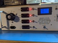
I had to add a 2nd soft-start module, as the 1320VA Variac tripped the main input breaker every 2nd time. Updated schematics attached in case someone wants to build a similar device. The bad thing is, the Variac input LED is broken (or badly soldered) and of course it's the one that is the most difficult to reach now that everything is cabled together.
On thing that I would do differently is to have a volt-meter on the Variac output. The digital module I used can't do it, it starts working from 180VAC, and there aren't much more front-panel estate anymore, so I will rely on the marking or an external multi-meter.
The box weights 16Kg, the Variac and the isolation transformer are heavy things, but they should last for the rest of my career if I don't mess up. There are fuses everywhere, and the left-most differential breaker is wired at the isolation transformer outputs. The front-panel markings are Dymo transparent labels, decent enough for the lab. The thing looks big but once I closed it and move it into it's final location it's less space than the individual boxed things and easy to reach.
An interesting aspect is the output of the isolation transformer. With 240V main, I get 250V at its outputs when unloaded. That's still within 230V + 10%, but still a bit high. Thanks to Hardi's suggestion, I can wire the Variac after the isolation transformer, especially for vintage DUT which were designed for 220V.
Initial inspiration came when I watched "MendItMark" Youtube channel, he is so well organized I thought I can sort out my lab better if I box all my devices with switches, LEDs and and fuses. Thanks to all contributors for the ideas and feedback.
Attachments
Variac's are like toroids. If you disconnect power at the peak of the cycle they will be stuck with the internal field near saturation so they look like a dead short to the power when applied. Once applied they operate normally but that first cycle current can be 100A+ if its saturated. Using zero crossing triac controls instead of switches can ameliorate that issue.
You may be able to power the display separately from the measured voltage. Nicely executed box. You should test all the safety features. It can be a bad day when the safety feature doesn't work and you need it to work . . . Ask Boeing.
You may be able to power the display separately from the measured voltage. Nicely executed box. You should test all the safety features. It can be a bad day when the safety feature doesn't work and you need it to work . . . Ask Boeing.
- Home
- Design & Build
- Equipment & Tools
- power distribution on the lab bench, is this safe and complete?