Power Buffer with ECX10N20/ECX10P20.
Delivers more than 20 Watt at THD 1% into 8 Ohm.
Here I feed the buffer with opamp OPA552.
Distortion at 1 Watt is only 0.008%
The Fourier shows an interesting spectrum.
H2 and H3 is way above the rest of the harmonies.


Delivers more than 20 Watt at THD 1% into 8 Ohm.
Here I feed the buffer with opamp OPA552.
Distortion at 1 Watt is only 0.008%
The Fourier shows an interesting spectrum.
H2 and H3 is way above the rest of the harmonies.

Looks like 406 mA per output FET, that equals near 100 Watts of total heat, but don't worry, lineup's simulator is burn proof, so is the opamp chosen which according to the datasheet can take max +/- 30 V, but let's assume it's only chosen to illustrate a case. 🙂
I use these output transistors sometimes, but never use the 0,47 emitter resistors.
Will give a little bit less higher order harmonics of crossover distortion.
Should be safe since you are well into negative tempco area at 400mA. I usually run mine at 150mA
Will give a little bit less higher order harmonics of crossover distortion.
Should be safe since you are well into negative tempco area at 400mA. I usually run mine at 150mA
Last edited:
Since OPS input is under influence of positive feedback(bootstrap) done via C1 & C4 I wonder what is the OPS input impedance plot alone ?, simulated let`s say in range from 5Hz up to 20Khz ?
btw ,IMHO , B+need to be raised to about +48V but IQ per each ECX device need to be reduced to about 150-200mA max.
btw ,IMHO , B+need to be raised to about +48V but IQ per each ECX device need to be reduced to about 150-200mA max.
Attachments
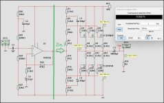
The voltage gain of the output stage is about 0.9. Thus, R2/R20 still see 1/10 of the output swing. The input impedance is about 5.6K*10/2=28K.Since OPS input is under influence of positive feedback(bootstrap) done via C1 & C4 I wonder what is the OPS input impedance plot alone ?,
I can agree with some critique of Lineups designs. Most the concern is usually phase margin/ stability for feedback designs.Looks like 406 mA per output FET, that equals near 100 Watts of total heat, but don't worry, lineup's simulator is burn proof, so is the opamp chosen which according to the datasheet can take max +/- 30 V, but let's assume it's only chosen to illustrate a case. 🙂
This is "impedance converting amplifier" or whatever you want to call it.
No feedback No gain high current buffer.
60 volt opamp on 40 volts not a big deal. Just depends on total output current needed to drive the " impedance converter" to full power at high frequency. Max current of 552 with thermal pad package is 380 ma.
So having seen a wash of " ok" to complete nonsense " turd " discrete solutions to drive such buffers.
I have said to myself why do people waste time with discrete buffers. Since there is plenty of opamp solutions.
I dont doubt his decision for 380ma High Voltage opamp. It is good choice.
And I do know Lineup has a very good catalog of high voltage opamps. Since he has simulated almost all of the candidates.
This case the input impedance of the buffer and the current to drive it was the concern. So aside from plenty of low current options.
High current and enough bandwidth would be the choice.
since these no feedback buffers tend to have garbage distortion anyways.
3 MHz 6MHz 12 MHz does it matter? 552 still remains at 12MHz far as I remember.
Since compensation is only needed for low gain, the input opamp has enough gain to likely ignore any compensation.
Stability and of course actual low distortion would be a issue if the output buffer was included in the feedback loop.
Current sharing and high frequency oscillation is always a concern with parallel laterals.
Excuses for them to not use current sharing resistors gets ignored. Finally somebody put high value resistors in a lateral design.
Since the thermal stability excuses dont work anymore to remove them.
Maybe the final real solution for parallel lateral problems , no feedback.
Last edited:
About 28K for OPS Z-in. is very high input impedance, I view such a simple and high-quality OPS circuit designed by Lineup from the position of a potentially very high-quality and very good-sounding A(b)-class hybrid amplifier, where let`s say one EL84 tube connected in a triode mode could easily drive such OPS providing sufficient voltage and current HQ gain , I should also add that I particularly like that type of OPS because it does not require any DC protection towards the speaker.The voltage gain of the output stage is about 0.9. Thus, R2/R20 still see 1/10 of the output swing. The input impedance is about 5.6K*10/2=28K.
@WhiteDragon Thanks for your reply, I agree with your assessment, I just noticed I have misread the schematics, somehow made previously up in my mind this was a double voltage supply, i.e. +/- 40 V, but it's just a single voltage supply, so the power burned up in the out put stage should instead be 40 V x (3 x 406 mA) which is roughly 50 W, and as well, the opamp is now operating within V supply spec.
- Home
- Amplifiers
- Solid State
- Power Buffer F4 Style with EXICON Lateral MOSFETs