Hey guys!
I've been simulating and implementing a power amp that I will use as a guitar amplifier. I have encountered two main problems that I can't just find a solution and I haven't seen many people talking about it.
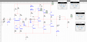
The first problem is the DC current at the Q4`s collector which is around 900mA. How could I limit it to a 100mA level? I have to limit Q9's emitter current that goes into Q4's base? Also, the DC voltage level at the speaker (represented by R25) is 250mV, and if I increase the feedback factor it increases the DC level at the output. There is a way I can have more gain without compromising my output? How can I decrease the output level? Should I use some kind of filtering with caps at the output?
Thank you all for reading the post and for the further considerations!
I've been simulating and implementing a power amp that I will use as a guitar amplifier. I have encountered two main problems that I can't just find a solution and I haven't seen many people talking about it.
The first problem is the DC current at the Q4`s collector which is around 900mA. How could I limit it to a 100mA level? I have to limit Q9's emitter current that goes into Q4's base? Also, the DC voltage level at the speaker (represented by R25) is 250mV, and if I increase the feedback factor it increases the DC level at the output. There is a way I can have more gain without compromising my output? How can I decrease the output level? Should I use some kind of filtering with caps at the output?
Thank you all for reading the post and for the further considerations!
Attachments
Q4 current should be controllable via the vbe multiplier Q12. Just put a short across Q12 for now, the current should fall to zero.
The DC input resistance should equal RF2. As a test, apply a short across C12 and make R1 equal 8K.
See if that corrects the offset and excess bias current.
The DC input resistance should equal RF2. As a test, apply a short across C12 and make R1 equal 8K.
See if that corrects the offset and excess bias current.
Mooly, thanks for the reply!
I've modified R1 to be 8k and I`ve shorted the Vbe multiplier circuit. The DC current obtained is 7.1uA and the DC level at the output is around -23mV. This means that the bias point without any input voltage is correct?
I took out the short around the input cap to see if the amp still works and the current at Q4 goes to 983mA and the voltage at the output goes to 200mV. Should I match Zin from Q1 and Zin from Q2?
More... your 1 ohm emitter resistors are a bit to high in value. Try 0.22 or 0.33 ohm. Even that is not optimum but it will aid quiescent current stability.
A real amplifier should be AC coupled at its input.
A real amplifier should be AC coupled at its input.
I see. I've changed the emitter resistors to this value. I have a preamp that decouples the signal already, so I will integrate both systems afterwards when I understand what's wrong or what I am misunderstanding.
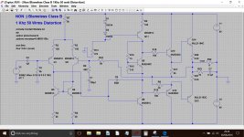
I'm out of time for today but it needs to look like this. This is a quick rehash of Doug Selfs blameless class B.
Look at the AC coupling at the input.
You will need to alter your bias preset to get the current you want... also the models and simulator you are using will give slightly different results to mine.
This is running 100ma bias current and the offset is under 4 millivolts.
Look at the AC coupling at the input.
You will need to alter your bias preset to get the current you want... also the models and simulator you are using will give slightly different results to mine.
This is running 100ma bias current and the offset is under 4 millivolts.
Attachments
I'll take a look at it. Thank you Mooly. I think I'll go back to LTspice. I've got too many simulation errors using Multisim 🙁
I got a 5mV offset but the bias current is 1.056A =O
I got a 5mV offset but the bias current is 1.056A =O
Change r10 or r11 to a 47R pot and you will be able to trim output dc offset.
Once the dc offset is <> 0mv you can adjust bias current.
Once the dc offset is <> 0mv you can adjust bias current.
Actually with the voltage source set to 7.4mV as you did it gives me a 100mA bias current. How can I control the current bias if I put a higher voltage at the input?
Yes, the bias is set by the multiplier only. The 7.4mv was a carry over from the original DC coupled simulation where I added it to get zero volts DC offset.
Adding the 1uF input cap to your version means that any DC present in the source is irrelevant.
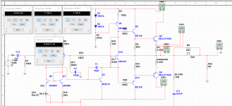
Try replacing your trimmer with two separate resistors like I have done, and alter the lower value resistor to get your desired current.
Adding the 1uF input cap to your version means that any DC present in the source is irrelevant.
Try replacing your trimmer with two separate resistors like I have done, and alter the lower value resistor to get your desired current.
Mooly,
I've corrected three problems: I've decoupled the input as you did; I put the shunt resistor equal to RF2; I've corrected the DC level at the output and is close to zero. Till now it works.
I got confused in a point. Please correct me if I'm wrong:
I have to set the quiescent current at my output transistor in a point that is little as possible in order to not have crossover distortion. I can get this current by setting a small sine wave in the input of the PA and by modifying the Vbe smaller resistor. Thus, I can check the current that goes through the emitter resistors at the output BJT and find a point that has no crossover distortion. When I do this I get a constant current less than 100mA. If I put an input of 1V I get a constant current of 1.12A and the AC current is 1.354Amps. The ideal case is to have a DC current of 100mA even with the maximum level I expect at the input?
I'm not familiar with Multisim, however if your DC conditions are correct (no offset and 100ma in the output stage) then that all sounds good.
When listening to the amp you will find that crossover distortion disappears audibly from using as little as a couple of milliamps bias current. In the real amp you would make your R11 a 1k preset.
When listening to the amp you will find that crossover distortion disappears audibly from using as little as a couple of milliamps bias current. In the real amp you would make your R11 a 1k preset.

Cool! Got basically the same THD as you. So basically the bias at 1Amps when 1V is applied to the input is correct?
Wooho!
Wooho!
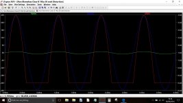
When signal is applied the current will increase as power is developed in the load. The total current then becomes a dynamic value, constantly changing.
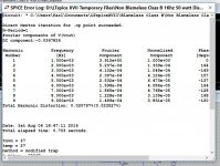
This shows Vin (1 volt peak) and Vout together with the current in the output stage. I'm still using the 0.33 ohms for this simulation.
This shows Vin (1 volt peak) and Vout together with the current in the output stage. I'm still using the 0.33 ohms for this simulation.
Attachments
- Status
- Not open for further replies.
- Home
- Live Sound
- Instruments and Amps
- Power Amp - Problem with DC levels