I've gone through this power amp and replaced the following parts that tested bad:
-the PNP driver transistor tested open and was replaced with an MJE15029. It was already an old NTE replacement when I received it.
-the two 1n914 diodes around it also tested open
I'm getting sound. However it sounds like a very poorly biased transistor. It's fuzzy/spitty sounding with low volume. The volume is only full for a split second when it powers up and powers down.
Where do I look?
I have a scope, but it's packed up. I will get it out if I have to. For now I've got an earphone protected from DC by a 0.1uF cap in order to probe around the circuit and listen to the signal. I have good sound at the output (loaded by R27 -- a 1.5k resistor) with no speaker attached. If I attach the 15" 8 ohm speaker I get the sound described above.
EDIT: to add...
All caps test good (no shorts. electrolytics range up and range down on an ohm meter). All diodes test good. All transistors (including the OP transistors pulled out of circuit) pass a diode test. Rail voltage is correct.
Attachments
Last edited:
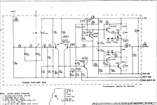
Are you getting 1/2 your supply at the + side of C14 you should be getting app 38v also check the bias current across R26 other than that you will need to get you scope out as you may have oscillation issue the circuit is also missing the zobel network.
Lack of drive current will do that.
Check the current feed resistors R18 & 19 and the bias voltage between the driver transistor bases. Should be around 2volts ish.
Agree with Bruce, check for half rail on the output. Zobel network not needed for this design as the MJ802 transistors cut off at 2MHz and the base - collector capacitances stop any HF.
Last edited:
Lack of drive current will do that.
Check the current feed resistors R18 & 19 and the bias voltage between the driver transistor bases. Should be around 2volts ish.
Agree with Bruce, check for half rail on the output. Zobel network not needed for this design as the MJ802 transistors cut off at 2MHz and the base - collector capacitances stop any HF.
Will check those voltage points.
Can MJ802s replace (or possibly replace) the RCA 40411? I had read that the company who designed this amp hand sorted 40411s (or maybe 3055s) after testing them and that not all survived running at load. I think these post homotaxial versions of the RCAs in this amp. Not sure if 1979 RCA 2N3055 transistors are epitaxial or not. I'd heard the 40411 is a 2n3055. I don't claim to know the history behind all of this.
Ok some voltages:
-77 rail
-36.5 at C14 positive
-0.6mV across R26 i.e. 2.5mA through it at idle.
Will look at r18 and 19 voltages.
-77 rail
-36.5 at C14 positive
-0.6mV across R26 i.e. 2.5mA through it at idle.
Will look at r18 and 19 voltages.
Ok I measure around 19.5v across each r18 and r19 (both 1k5 resistors above Q4).
This seems to align with the 37.5v marked for the collector of Q3.
Oh... And yes. Right at 2v across the bases of Q5 and Q7.
This seems to align with the 37.5v marked for the collector of Q3.
Oh... And yes. Right at 2v across the bases of Q5 and Q7.
Last edited:
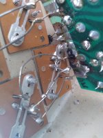
Ok... Found the problem. While I was replacing known bad components (at 2am) I got sloppy with the soldering iron and a flung blob bridged the socket of one of the power transistors. Thankfully i had substituted 2n3055s as an experiment because I lost one if them in the process of noticing (with a big spark) my solder bridge as I jarred the amp board while listening. Better one of those than the original RCA!
Attachments
Last edited:
The 40411 is an MJ802 (200W). A 2n3055 will work OK but don't expect too much power (70W max).
Good to know. I'm putting the originals back in there. I was glad to have killed a 2n3055 while troubleshooting instead of the real thing.
Thanks for the pointers BTW. You were right on the money with your 2v base to base voltage for the drivers.
- Home
- Amplifiers
- Solid State
- Power Amp clean without load... quiet and fuzzy/poppy with load