Can I replace 25k pots with 10k in here?:
Thanks
An externally hosted image should be here but it was not working when we last tested it.
Thanks
Do you really need to use that circuit ? It's not the best TC circuit you could have, as it will be noisy !
If you'ld like a better one, & with 10k pots, let me know what Bass & Treble frequencies you want, & i'll post one of my designs for you.
If you'ld like a better one, & with 10k pots, let me know what Bass & Treble frequencies you want, & i'll post one of my designs for you.
I'm looking for 80Hz and 12kHz. Reason why I went with mentioned schematics is because it adjusts only the frequency I need and has no or little effect on other freq. Like in graphical eq you control only freq that you need. It also does not mess with signal phase.
Hey, thanks for help!!! 🙂
Hey, thanks for help!!! 🙂
What about 1k pot? Shouldn't they have less Johnson notice? If so, maybe 1k?
Can find both 10k and 1k cheap on eBay, but not 25k....🙁
Can find both 10k and 1k cheap on eBay, but not 25k....🙁
.
You can't change anything in a tone control circuit without recalculating the entire circuit. All the components work together.
In my opinion tone controls make such a mess of phase relationships that johnson noise is a strictly secondary consideration. But then, in my opinion johnson noise is too much worried about anyway. How often do you turn the volume to max with your ear next to a speaker? Headphone amps can be another story, of course.
According to Douglas Self the input impedance of a tone control circuit is surprisingly low, although he doesn't give an exact figure that I'm aware of. This might make it wise to feed a tone control circuit with the output of a buffer, which has an output impedance of approximately nothing.
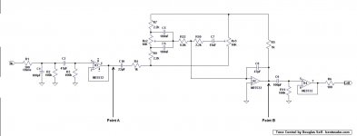
Below is a shameless rip of a tone control circuit by the same Mr. Self, or actually his circuit is between points A and B, the rest is me fooling around with inputs and outputs. This circuit doesn't really meet your requirements, but I happen to have the images lying around and I thought they might be of interest in a general kind of way.
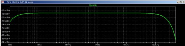
The first image is the circuit, of course, and the second is the LTspice frequency response plot at Point A.
The third image is the plot at Point B, both bass and treble controls being turned from minimum to maximum. Both being turned at the same time, which is why there are multiple plots. In real-time there would be a single plot for the bass response, and a single plot for the treble response.
All of which might be of interest because this is pretty much similar to the plots of all the tone control circuits I've looked at, which is several. I don't know how accurate LTspice is when plotting these (I expect very accurate), but they all come out pretty similar, which makes me suspect that regardless of what a manufacturer or designer claims this is what you're going to get.
.
You can't change anything in a tone control circuit without recalculating the entire circuit. All the components work together.
In my opinion tone controls make such a mess of phase relationships that johnson noise is a strictly secondary consideration. But then, in my opinion johnson noise is too much worried about anyway. How often do you turn the volume to max with your ear next to a speaker? Headphone amps can be another story, of course.
According to Douglas Self the input impedance of a tone control circuit is surprisingly low, although he doesn't give an exact figure that I'm aware of. This might make it wise to feed a tone control circuit with the output of a buffer, which has an output impedance of approximately nothing.
Below is a shameless rip of a tone control circuit by the same Mr. Self, or actually his circuit is between points A and B, the rest is me fooling around with inputs and outputs. This circuit doesn't really meet your requirements, but I happen to have the images lying around and I thought they might be of interest in a general kind of way.
The first image is the circuit, of course, and the second is the LTspice frequency response plot at Point A.
The third image is the plot at Point B, both bass and treble controls being turned from minimum to maximum. Both being turned at the same time, which is why there are multiple plots. In real-time there would be a single plot for the bass response, and a single plot for the treble response.
All of which might be of interest because this is pretty much similar to the plots of all the tone control circuits I've looked at, which is several. I don't know how accurate LTspice is when plotting these (I expect very accurate), but they all come out pretty similar, which makes me suspect that regardless of what a manufacturer or designer claims this is what you're going to get.
.
Attachments

Last edited:
PS take a look here:
items in Thai Shine store on eBay!
DISCLOSURE: I have no association with these people except I send them money sometimes.
items in Thai Shine store on eBay!
DISCLOSURE: I have no association with these people except I send them money sometimes.
PS take a look here:
items in Thai Shine store on eBay!
DISCLOSURE: I have no association with these people except I send them money sometimes.
Looks like they don't have dual pots...
The original schematics was "borrowed" from Designing A Pocket Equalizer For Headphone Listening by Chu Moy from Designing A Pocket Equalizer For Headphone Listening | HeadWize
From the text (figure 6 in first post):
The Wien bridge equalizer in figure 6 uses dual resonant filters to isolate the effect of the bass and treble controls to the center frequencies. A voltage divider at the input sets the signal level into the filter which is then varied by feeding back the bandpass response into the differential input of the opamp. The per-band gain is ±9 dB. Each bandpass consists of a pair of RC filters, so the slope of boost or cut is 6 dB/octave on either side. Even when the controls are set at maximum gain or cut (figure 7), the filters have little or no effect on the low, middle and high portions of the audio spectrum.
I actually recently bought Small Signal Audio Design, 2nd ed, by Douglas Self. Very informative reading!
From the text (figure 6 in first post):
The Wien bridge equalizer in figure 6 uses dual resonant filters to isolate the effect of the bass and treble controls to the center frequencies. A voltage divider at the input sets the signal level into the filter which is then varied by feeding back the bandpass response into the differential input of the opamp. The per-band gain is ±9 dB. Each bandpass consists of a pair of RC filters, so the slope of boost or cut is 6 dB/octave on either side. Even when the controls are set at maximum gain or cut (figure 7), the filters have little or no effect on the low, middle and high portions of the audio spectrum.
An externally hosted image should be here but it was not working when we last tested it.
I actually recently bought Small Signal Audio Design, 2nd ed, by Douglas Self. Very informative reading!
I immediately yield to Mr. Moy, he knows a teensy bit more than I do.
However, you still can't go around changing component values just because you feel like it. Or you can, of course, but everything in an electronic circuit affects everything, so the results of random changes are purely in the hands of the Electronic Gods, who are not overly generous with their magic smoke.
However, you still can't go around changing component values just because you feel like it. Or you can, of course, but everything in an electronic circuit affects everything, so the results of random changes are purely in the hands of the Electronic Gods, who are not overly generous with their magic smoke.
I with I knew how to calculate stuff, but I don't.... 🙁
maybe there is a kind soul here somewhere on the forum....
maybe there is a kind soul here somewhere on the forum....
<< Looks like they don't have dual pots... >>
Oh dual pots, right. For these you pretty much have to go to https://www.smallbearelec.com/home.html or to one of the grownup suppliers, such as Mouser.
Mouser does charge for shipping, but if you can get an order of any size together it's probably worth it because for lightweight orders you can get out with a minimal 5 dollar shipping charge.
There's also Tayda and Futurlec, both of them offshore Asian. Check those out on YouTube.
DISCLOSURE: None of these people send me any money. Not ever. None. SOBs.
Last edited:
<< I with I knew how to calculate stuff, but I don't...maybe there is a kind soul here somewhere on the forum.... >>
Well, there's Zero D
He said he'd post a circuit for you.
There's also this on Google: https://www.google.com/webhp?complete=0&gws_rd=ssl#complete=0&q=calculator+tone+control+circuit
Well, there's Zero D
He said he'd post a circuit for you.
There's also this on Google: https://www.google.com/webhp?complete=0&gws_rd=ssl#complete=0&q=calculator+tone+control+circuit
80Hz is rather high, i would go for 50Hz or 60Hz, but if that's what you Really need. 12kHz is fine & what i have.
1k pots combined with the other required components, would probably be too low for most OPA's to drive comfortably. 10k are no issue though. Lots of places sell 10k Dual Linear Pots, eg Mouser & Farnell.
I understand your desire for the GEQ type of response, but i would redesign that one, or design a 2 band "normal" GEQ.
If you go with the D.Self design posted by bentsnake, the output will be Inverting, which is not what you "might" want. So i would either make U3 inverting & miss off U4, or invert U4. Adjust the C5/C6 values to suit the Bass, & C7 for Treble.
<< If you go with the D.Self design posted by bentsnake.. >>
Hold everything! I was just doing a might-be-of-interest post, not making a suggestion. We already know the circuit I posted doesn't meet the stated requirements. I yield again.
Hold everything! I was just doing a might-be-of-interest post, not making a suggestion. We already know the circuit I posted doesn't meet the stated requirements. I yield again.
80Hz is rather high, i would go for 50Hz or 60Hz, but if that's what you Really need. 12kHz is fine & what i have.
1k pots combined with the other required components, would probably be too low for most OPA's to drive comfortably. 10k are no issue though. Lots of places sell 10k Dual Linear Pots, eg Mouser & Farnell.
I understand your desire for the GEQ type of response, but i would redesign that one, or design a 2 band "normal" GEQ.
If you go with the D.Self design posted by bentsnake, the output will be Inverting, which is not what you "might" want. So i would either make U3 inverting & miss off U4, or invert U4. Adjust the C5/C6 values to suit the Bass, & C7 for Treble.
Ok, now I see what post you were talking about. 🙂
Sure, 10k pots are fine.
2 band "normal" GEQ will be fine as well.
My reasons where because Makie has 80Hz and 12kHz in their mixers Mackie - Onyx 820i
For EQ frequency selection question I would start new thread in the forum.... Including talking about common sizes of badrooms and living rooms with calculating resonating freq of those rooms and freq where sound response goes down...
But, maybe you have your own, specific reasons for 50 and 60Hz? And 12kHz?
Sure, 10k pots are fine.
Good
2 band "normal" GEQ will be fine as well.
I'll post something soon.
Mackie doesn't make HiFi. Their mixers are for PA etc.
50 or 60Hz And 12kHz i've found are ideal for home use with a wide range of material.
50 or 60Hz And 12kHz i've found are ideal for home use with a wide range of material.
Lets go with 50Hz then.
Is there a way to make schematics with the pot that will adjust from 50Hz to say 100 Hz? Just wondering...
I simmed the Wien circuit & found that pot dB variation appears to be irregular = non linear. Also the component values given for the high f's didn't seem to check out ! I wouldn't recommend it.
So i would Strongly suggest a Graphic type EQ for both f's, the bandwith = Q can be tailored not to interfere with other f's as regular tone controls do. This, i think, would be more to your liking, from what you've said. However, it will require 4 OPA's per channel for stereo. This isn't an issue though, as they can be low noise ones.
OK, so 50Hz & 12kHz.
If you want to change the f's from 50Hz to say 100 Hz you could switch in/out extra/less capacitors on that section. If you wanted to vary the f's then your talking about something different = a parametric EQ. With one of those you can do that, & vary the Q & gain/loss.
I'll design a GEQ for you though.
- Status
- Not open for further replies.
- Home
- Source & Line
- Analog Line Level
- Pot values for tone control - from 25k to 10k