Hello all --
While on the subject on grids (see my other active thread) - I remember another thread here that got me thinking about a use for "worthless" pentagrid tubes. Seems there are those who use what is typically the screen grid in pentodes as the control grid and the suppressor grid as the screen (or other combos as well).
Has anyone every played with Pentagrid tubes in this fashion? I tried looking up the transconductance first to see if it was worth the trouble (the 6ba7 was the only one that came quickly to mind). But only "conversion" transconductance was listed which seemed very low - even though max plate dissipation looked more promising. thx for your time.
Conversion transconductance is what pentagrid tubes are all about. They are used as rf mixers in communications gear.
You can use them for other purposes but you have to respect the electrode voltages. You can't, for example, expect much plate current if the screen is at a low potential. And the suppressor is not designed to carry current.
You might find some early diagrams using the 6L7 tube an inspiration.
You can use them for other purposes but you have to respect the electrode voltages. You can't, for example, expect much plate current if the screen is at a low potential. And the suppressor is not designed to carry current.
You might find some early diagrams using the 6L7 tube an inspiration.
Physically, the stuff behind G3 looks like a cathode, so you get triode/pentode-like characteristics when you start playing with G3 and G4 (they don't usually give you G4 independent of G2, so you're limited to pentode characteristics). This is exactly like the suppressor/second control grid curves obtained in this thread:
http://www.diyaudio.com/forums/tubes-valves/160240-suppresor-grid-used-feedback.html
Basically, when G3 is wide open, you get the ordinary pentode curves. Now, imagine, if you will, that these curves are triode curves, and the reason they flatten out at high plate voltages is not from the screen grid, but because the cathode is starved. Replace the cathode-G1-G2 stuff with a black box that emits a limited current. Now G3 looks exactly like G1 on a starved triode, and biasing it has the effect of shifting the plate curves to the right, changing cutoff, but not changing the saturation current (because that's limited by the cathode).
Physically, G3 diverts current from plate to screen, so the actual cathode current is approximately constant. That can be dangerous for the screen, so you want to use signal currents here. (This effect can be used as a Muntzed LTP, see g3 driven phase inverter.)
Now, if you put a screen after this "virtual starved triode" thing, you get constant current again, because the screen grid basically isolates just one point on what used to be the plate curves. So the real plate curves seem to be usual plate curves (start at 0, go up steeply, saturate by ~50V), this time with current limited to the value set by G3. But that limit is, in turn, set by the limit of the virtual starved cathode, which is controlled by G1. The current is thus the product of G1 and G3 -- a one-quadrant multiplier, perfect for mixing!
You don't want to use the screen grid for anything, because it's acting as a virtual anode. You can use the control grids for anything -- over a certain range, the output is simply the product of the two grid voltages, so you can use it effortlessly for multiplication, mixing, volume control and so on.
Incidentially, transistors have it just as easy -- transconductance is directly proportional to bias current, so you can make a multiplier by controlling the tail current in an LTP. Cool stuff.
Tim
In fact I did. I used two 6AU6s for oscillators, and a 6BE6 to mix them. Worked quite well. Never did implement volume control though... should do that some day. 😀
Tim
Tim
This is exactly like the suppressor/second control grid curves obtained in this thread:
http://www.diyaudio.com/forums/tubes-valves/160240-suppresor-grid-used-feedback.html
Yes this is the thread that stimulated my thinking -- appreciate your tie in Tim. Forgot about the 6le8 discussion - I gotta bunch of those.
Re-reading that thread tempts me to hijack my own thread - I am very interested to turn loose the braintrust on var-mu compression!! Specifically - how simply (fewest tubes - components) can it be done for a lower fidelity instument amp setting -- maybe a new thread.
Last edited:
In fact I did. I used two 6AU6s for oscillators, and a 6BE6 to mix them. Worked quite well. Never did implement volume control though... should do that some day. 😀
Tim
I would kill for that schematic!!! Please please please!
I tried making a couple versions of a tubed stereo dynamic range expander using pentagrid tubes based on an article I found. The sound quality wasn't that good.
Has anyone every played with Pentagrid tubes in this fashion? I tried looking up the transconductance first to see if it was worth the trouble (the 6ba7 was the only one that came quickly to mind). But only "conversion" transconductance was listed which seemed very low - even though max plate dissipation looked more promising. thx for your time.
Never tried that, though there's no reason why you couldn't use 'em. Consider it a type of cascode with a pentode sitting on top of a triode. Try some loadlines, guesstimate the THD figures, and see what you get. If you actually wire up a circuit, then you'll have to play around with screen voltages and bias levels to minimize the actual distortion.
Whether it's worth it or not is a whole 'nother problem.
If worst comes to worst, just keep 'em for radio projects or trade 'em for more useful types.
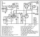
This one from October 1949 of "Radio & Television News" uses the pentagrid valve (tube) as both one oscillator and the mixer.
The Wikipaedia article on "Pentagrid Converter" is interesting in that it explains how the same 5-grid tube was designed and operated differently in the USA and in European receivers, to give much the same overall result.
The Wikipaedia article on "Pentagrid Converter" is interesting in that it explains how the same 5-grid tube was designed and operated differently in the USA and in European receivers, to give much the same overall result.
Attachments
- Status
- Not open for further replies.
- Home
- Amplifiers
- Tubes / Valves
- Possible use for Pentagrid tubes??