Hi,
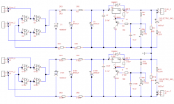
can somebody let me know if the below circuit will work. I am trying to get both positive and negative voltages using 2 LM350 by connecting their output in series and using their junction as the ground.
Also I am taking negative voltage from a capacitor and feeding it to one of the regulators but with the right polarity.
Thanks
Attachments
![20150124_122100[1].jpg](/community/data/attachments/431/431737-05a9f0cb6590bbe289a42693cef8d027.jpg?hash=Banwy2WQu-)
Could you please help me understand. Can you tell me the 2 points which is causing the short.
Thanks
Thanks
Look at the bottom regulator... its output is tied directly to its input.
Move the bottom regulator and its circuitry so it is in the ground line between the two caps at the upper regulator, the ones marked 58V and .1u.
Move the bottom regulator and its circuitry so it is in the ground line between the two caps at the upper regulator, the ones marked 58V and .1u.
Thanks, got it.
Ok, will this modification work?
Ok, will this modification work?
Attachments
![20150124_152847[1].jpg](/community/data/attachments/432/432288-411eeec9af7721c15d4f6a8f0e097815.jpg?hash=QR7uya93Ic)
Last edited:
iinself, you have the answer. I can only add, think only of three output connections. Not the four that have you stuck.
If one requires a dual polarity supply, then one must have:
a dual secondary windings and dual rectifiers and dual PSUs, that can be series connected at their OUTPUTs.
or
a centre tapped winding with a single bridge rectifier and series connected smoothing caps feeding opposite polarity PSUs.
This difference for dual polarity supplies has been stated clearly on this Forum hundreds of times.
When will our Members learn to research their projects?
The OP only shows his circuit after the filter caps.
His error is using the ground of one reg as the input of the other reg. It should have the ground of one reg as the output of the other reg (ie, post #4).
BTW the O2 project (for example) has a third +/- psu option.
His error is using the ground of one reg as the input of the other reg. It should have the ground of one reg as the output of the other reg (ie, post #4).
BTW the O2 project (for example) has a third +/- psu option.
Ok, thanks. So I HAVE to use a negative regulator?
Yes, because you have a common input ground for the two regulators.
You can only use two identical regulators for a +/- supply IF there are two isolated (not connected together) windings, each with a full wave bridge rectifier,
each feeding a positive regulator, and with the ground of the positive regulator tied to the positive output of the other regulator.
The "ground" of the other regulator then becomes the negative output, and the common connection point becomes the output ground.
In other words, you have two identical regulator circuits with the outputs in series. The inputs are NOT connected together in any way.
I thought the post #4 change would work. It sims at +/- 34v out with the given parts values, into 1k loads.
I thought the post #4 change would work. It sims at +/- 34v out with the given parts values, into 1k loads.
Ok, I am confused 🙂 Will this work?
The OP only shows his circuit after the filter caps.
His error is using the ground of one reg as the input of the other reg. It should have the ground of one reg as the output of the other reg (ie, post #4).
BTW the O2 project (for example) has a third +/- psu option.
Sorry. The circuit before the caps is basically a centre tapped transformer with a single bridge rectifier and series connected smoothing caps feeding opposite polarity PSUs as mentioned by AndrewT. Will this modification work.
Center tap transformers are a bust here and most places, better keep them separated eg use double windings, add anther bridge and filter cap keeping them separate all till the end , only joining them at the V regs outputs plus to minus.
So you're saying I found a quirk in the circuit simulator software?I thought the post #4 change would work. It sims at +/- 34v out with the given parts values, into 1k loads.
I maintain that it does. Whether it is suitable for your application is another question. Statements of bipolar supplies "...must...," "...only...," "...center-tapped...," "...isolated..." are technically wrong, though such a bipolar supply may be necessary in your case.Ok, I am confused 🙂 Will this work?
.................You can only use two identical regulators for a +/- supply IF there are two isolated (not connected together) windings, each with a full wave bridge rectifier,
each feeding a positive regulator, and with the ground of the positive regulator tied to the positive output of the other regulator.
The "ground" of the other regulator then becomes the negative output, and the common connection point becomes the output ground.
In other words, you have two identical regulator circuits with the outputs in series. The inputs are NOT connected together in any way.
.......... The circuit before the caps is basically a centre tapped transformer with a single bridge rectifier and series connected smoothing caps feeding opposite polarity PSUs as mentioned by AndrewT. Will this modification work.
Center tap transformers are a bust here and most places, better keep them separated eg use double windings, add anther bridge and filter cap keeping them separate all till the end , only joining them at the V regs outputs plus to minus.
If one requires a dual polarity supply, then one must have:
a dual secondary windings and dual rectifiers and dual PSUs, that can be series connected at their OUTPUTs.
or
a centre tapped winding with a single bridge rectifier and series connected smoothing caps feeding opposite polarity PSUs.
..................
Yes, because you have a common input ground for the two regulators.
You can only use two identical regulators for a +/- supply IF there are two isolated (not connected together) windings, each with a full wave bridge rectifier,
each feeding a positive regulator, and with the ground of the positive regulator tied to the positive output of the other regulator.
The "ground" of the other regulator then becomes the negative output, and the common connection point becomes the output ground.
In other words, you have two identical regulator circuits with the outputs in series. The inputs are NOT connected together in any way.
Sorry. The circuit before the caps is basically a centre tapped transformer with a single bridge rectifier and series connected smoothing caps feeding opposite polarity PSUs as mentioned by AndrewT. Will this modification work.
Center tap transformers are a bust here and most places, better keep them separated eg use double windings, add anther bridge and filter cap keeping them separate all till the end , only joining them at the V regs outputs plus to minus.
referring to my post?I maintain that it does. Whether it is suitable for your application is another question. Statements of bipolar supplies "...must...," "...only...," "...center-tapped...," "...isolated..." are technically wrong, though such a bipolar supply may be necessary in your case.
must is technically correct?
Or Rayma's post where isolated is technically correct?
Or Iinself's post where centre tapped is technically correct?
Sofspud, are you ready to argue with three Members when it appears to most you are clearly wrong?
- Status
- Not open for further replies.
- Home
- Amplifiers
- Power Supplies
- Positive and negative voltages from 2 LM350