I see many modern speakers with vented type installed their port underneath the cabinet firing down towards the floor. I just wonder is there a calculation for the gap between the port and the floor, does anyone know? I don’t think it’s simply a rule of thumb. I believe designing a speaker is science, not merely art. So, it should be able to be explained for any reason by Physics and Mathematics.
The gap can (and will) act as an extension of the port, but unless the gap is very tight the difference will be tiny.
I did a measurement of something comparable here (see the port variants with "caps", impedance/tuning measurement in the next posting).
You can also calculate the surface of the gap at the port opening (port circumference * gap height). If that surface is similar or even smaller than the port cross section surface it will lower your tuning considerably. If not it will not change much.
Directing the port to the floor has two advantages:
- reduced tendency of flow separation at high levels (so high actually that you will probably not consider them acceptable, so it's a theoretical advantage only)
- reduced output of port and enclosure resonances, mostly if used above absorptive flooring material (carpet)
In better designs the port will fire downwards towards a plate that is part of the speaker (e.g. Revel Studio). This is done in order to avoid the gap under the speaker varying with floor type. The gap extends the effective length of the port enabling a shorter port within the speaker. In a serious design the shape of the bottom of the speaker and/or the standing plate will not be flat. The shape can be optimised with CFD software. Harman likely did this with expensive software like COMSOL but DIYers could use free software like OpenFOAM which is a bit more difficult to use but should give equally good results. I am not aware of examples though. Anyone?
The frequencies that a woofer br port work is typically 30-100 Hz. Respective wavelegth is 100-27cm, this means that contour of the port opening has no effect.
A downfire port might give some horn-like spl boost, but again I doubt that because of wavelength.
https://data-bass.com/#/articles/5cb4eb62079a580004e73249?_k=s052ln
A downfire port might give some horn-like spl boost, but again I doubt that because of wavelength.
https://data-bass.com/#/articles/5cb4eb62079a580004e73249?_k=s052ln
That's not entirelly true.this means that contour of the port opening has no effect.
The port contains air with a weight that is being accelerated an decelerated. Once the surface of the port opening gets very big (at the ends) the air movement distance and thus also the acceleration gets very small, thus having no relevant influence.
The end correction factors of ports include the moving air at the port ends and add some effective port length, depending on port diameter.
if however there is only a very small air gap at the port exit the respective air movement in the gap is still relevant and thus the air weight adds to the port and the tuning frequency will be lower.
Edit: I should add that flaring or guiding air flow of a port (e.g. also by directing it to the floor) has very little to do with an acoustic horn but is very relevant regarding turbulent/laminar air flow.
The frequencies that a woofer br port work is typically 30-100 Hz. Respective wavelegth is 100-27cm, this means that contour of the port opening has no effect.
It influences the rate of flaring which influences the effective length, behaviour at high velocities (i.e. when chuffing starts) and to a mild extent the damping of the resonance. Geometry in the right ballpark is unlikely to be critical in the sense of small variations creating big differences but there will be an optimum for the flaring. Note the air moving in and out of the port is effectively incompressible. The flaring influences this incompressible fluid motion which is moving relatively slowly at 10-20 m/s and not the 340 m/s of sound. It also involves more energy than the relatively weak compressible motion (i.e. sound).
It's not just 'modern' loudspeakers, it's been done in various forms for decades.I see many modern speakers with vented type installed their port underneath the cabinet firing down towards the floor.
There isn't "'a' calculation" as such since it varies with the design (enclosure / duct dimensions & target alignment, presence of an integrated plinth or incorporated damping etc.). So it's a multi-stage process, albeit not one that needs to be necessarily difficult or lengthy.I just wonder is there a calculation for the gap between the port and the floor, does anyone know?
That's because it isn't, although some may come into effect for, say, a down-firing design sans integrated plinth, to account for the effects of different floor coverings. These aren't likely to be huge, unless they're blocking the gap (which is just poor design & shouldn't trouble us here) as most carpets & underlay will only have relatively minor impacts on LF frequencies. However, since that is an infinite variable, it's not possible for a manufacturer to be exact in that particular case for obivous reasons. There are also instances like Avalon who have used essentially very low EBS style alignments and aren't very interested in behaviour around Fb as it's not being used for reinforcement as such.I don’t think it’s simply a rule of thumb.
Yes, it is, in both instances.I believe designing a speaker is science, not merely art. So, it should be able to be explained for any reason by Physics and Mathematics.
For rear facing ports, I have read that you need at least the diameter of the port distance from the wall. Aka at least 2" distance for a 2" diameter port.
Is a similar rule of thumb for floor pointed ports?
I too am trying to decide between bottom porting my towers, or going with a back port.
Is a similar rule of thumb for floor pointed ports?
I too am trying to decide between bottom porting my towers, or going with a back port.
Bottom firing 1st approximation
Rear firing 1st approximation is a function of the vent pipe's end correction = 0.61r
Rear firing 1st approximation is a function of the vent pipe's end correction = 0.61r
That distance or more will have hardly any affect on Fb (Frequency of box tuning).For rear facing ports, I have read that you need at least the diameter of the port distance from the wall. Aka at least 2" distance for a 2" diameter port.
No, as STV mentioned in post #2, the gap between the bottom of the cabinet and floor can (and will) act as an extension of the port, so should be designed using the end correction.Is a similar rule of thumb for floor pointed ports?
In practice, it is easier to fine-tune the Fb variation by adjusting the height of the cabinet from the ground.
What is the relevance of port tuning changing a few Hz from calculated?
Attenuating resonance- and puffing noise perhaps might be measured and heard at listening distance?
The only vented speaker I have are ht satellites in two liter box, no interest in testing with them...
Attenuating resonance- and puffing noise perhaps might be measured and heard at listening distance?
The only vented speaker I have are ht satellites in two liter box, no interest in testing with them...
A handful of Hz = not a lot in practice. But depending on implementation & setting the other aspects aside for a moment, it can be more than a few Hz. For e.g., if you drop a 12mm gap to 1mm, you'll likely (depending on your initial baseline) make a fairly major shift in alignment (double digit) & practical output. Another of those 'it depends on circumstance' situations...
So, I got my loaned little "sub" back for testing...
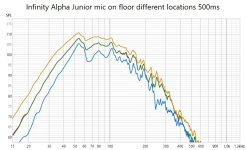
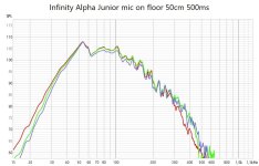
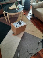
Infinity Alpha Junior from early years of this millenium. Port tuning 50Hz, 8" driver and the flared port are both on frontside. Speaker was on a thick carpet indoors, middle of the room. 500ms gating shows also room modes but represents well what we humans hear.
Indeed - there are measurable differencies when driver and port are downfiring vs.front. Port down has less problems. As well mic in the middle or edge of the port gives differencies.
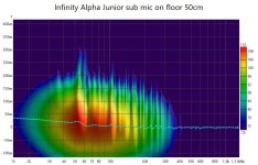
But differencies in my measurements are totally insignificant. Mic location changing a few centimeters gives more differencies. Wavelet spectrogram shows room modes.
Go ahead and prove me wrong, please!
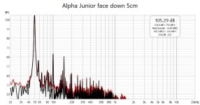
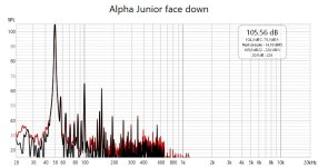
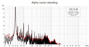


Last edited:
Ääh, the most significant picture missed notes

ps. In previous post's pics, spl of whole speaker and port only are not comparable. Port measurement signal was 20dB lower but mic closer to source
ps. In previous post's pics, spl of whole speaker and port only are not comparable. Port measurement signal was 20dB lower but mic closer to source
Last edited:
When doing a bototm firing vent i ensure sufficient room that the vent willnot be (significantly) affected by the proximity of the floor bass plate.
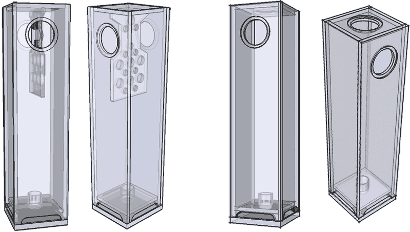
Note: your tower will be an ML-TL and cannot be properly modeled with reflex software.
dave

Note: your tower will be an ML-TL and cannot be properly modeled with reflex software.
dave
Out of academic curiosity I measured also my sealed downfire subwoofers of AINOgradients is same way.
From sweeps we can see the room mode peak at 50Hz, but also the eq I have set on dsp - neg. peak at 50Hz, low end boost (pos. peak at 30Hz) and acoustic LR2 xo.
Sine sweep at 50Hz and 105dB is much cleaner of noise but harmonic distortions are pretty similar
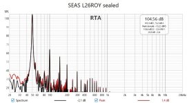

From sweeps we can see the room mode peak at 50Hz, but also the eq I have set on dsp - neg. peak at 50Hz, low end boost (pos. peak at 30Hz) and acoustic LR2 xo.
Sine sweep at 50Hz and 105dB is much cleaner of noise but harmonic distortions are pretty similar


Edit time over... distortion signal is of course steady 50Hz sine wave from REW's generator, not a sweep!
Wavelet spectrograms of br vs. sealed subwoofers, measured same way in same room. BR was standing ie. driver and port towards the mic. Sealed is downfire. So there is a small difference in how they excite room modes. Placement for listening is different.
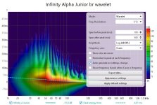
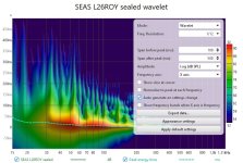
Wavelet spectrograms of br vs. sealed subwoofers, measured same way in same room. BR was standing ie. driver and port towards the mic. Sealed is downfire. So there is a small difference in how they excite room modes. Placement for listening is different.


Last edited:
- Home
- Loudspeakers
- Multi-Way
- Port that is firing towards floor