I bought the capacitors of Auricap and I read something which I think not.
The capacitor arrived in a small box, packed in a plastic bag containing mounting instructions.
One lead is black and the other one red. If the capacitor is used in the signal path the signal must enter through the black lead and get out through the red one.
If the capacitor is used as power supply bypass unit, the black lead Should be connected to ground and the red one to the + or - voltage. Finally, if the capacitor is used in loudspeakers crossovers, the red lead Should Be toward the + terminal and the black one towards the - one.
but how is it possible that a capacitor has polarity?
Here is what the maker of Auricaps has to say about which lead to attach where in which application.
Auricap High Resolution Capacitors: Application Notes
Auricap High Resolution Capacitors: Application Notes
It's not something I lose a lot of sleep over, but the idea is that a capacitor inevitably has an outer layer. That layer connected to earth is means the capacitor outer layer is grounded and doesn't radiate any signal to other components via common mode.
A similar radio frequency idea is that the outer layer of an inductor coil should be grounded.
Whether it makes any difference at audio frequencies is debatable, but you might as well get it right. Most capacitors aren't marked in any way that helps you make a decision, of course.
A similar radio frequency idea is that the outer layer of an inductor coil should be grounded.
Whether it makes any difference at audio frequencies is debatable, but you might as well get it right. Most capacitors aren't marked in any way that helps you make a decision, of course.
I sense, soon there will be someone stating something
about it being complete and utter...I admit, red and black
stockings look nice.
about it being complete and utter...I admit, red and black
stockings look nice.
As above its not a polarity but an indication of which side is the inner and outer foil. Here is a good example.. Jimmy’s Junkyard Blog Archive Observing Inner and Outer Foil of Some Popular Capacitors
I sense, soon there will be someone stating something
about it being complete and utter...I admit, red and black
stockings look nice.
LOL!
However, it does make for good marketing and product differentiation!
I gotta admit that I always match capacitor orientation on the two speaker crossovers just in case it makes a difference! 😀
At least it's making the same difference that way! It's tough being obsessive! 😱
At least it's making the same difference that way! It's tough being obsessive! 😱
Do you have to position the caps so the labeling is at the top, and all resistors so their colour codes can be read from left to right? I do...
Do you have to position the caps so the labeling is at the top, and all resistors so their colour codes can be read from left to right? I do...
EXACTLY! You want it to photograph well so you can read all the values easily! 😱
This must be far more important than any nonsense about common mode. 😀
Do you have to position the caps so the labeling is at the top, and all resistors so their colour codes can be read from left to right? I do...
As your interesting link has shown, there is indeed a measurable difference between the inner and outer layer leads.
Measurable? yes.
Audible? If it were consistently significantly audible, I'm sure virtually all cap makers would be identifying their inner and outer leads. Wouldn't you say?
Do you have to position the caps so the labeling is at the top, and all resistors so their colour codes can be read from left to right? I do...
caps, yes so i can show off that i used a good caps 😛
but for resistor, i put them the way i want 😀 .like the last ring goes to the ground, or vice versa 😀
This is turning into a FUN thread.
It's interesting, at least to my inner obsessive nature, that common mode radiation is reduced by physically shrinking the components.
So there MIGHT be something to be said for smaller 250V Polypropylenes rather than huge 630 or 1200V types. 😎
Also saves money on those ridiculous EXPENSIVE and HUGE exotic capacitors. Which are the very devil to fit on a circuit board. 😀
Measurable? yes. Audible?
Audible in a speaker, probably not, stuffed inside a valve amp in proximity to transformers radiating AC hum it could make all the difference. Hence i do it anyway. Why don't all manufacturers label them, i dunno..
And you put 'em inside the box...!?! 🙄🙁
put em inside box but omit the cover 😛
Steve, you sound like F. Zappa on stage ...
( it was the "penguin in bondage" introduction 😛 )
All I can say is that I've BEEN THERE with HUGE and OVERSPECIFIED capacitors! 😀
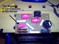
The below example is a huge 0.1uF 1200V jobbie that I somehow ended up with. Can't fault it of course, but probably overkill...😱
No idea about polarity, of course. 😕
Attachments
Also saves money on those ridiculous EXPENSIVE and
HUGE exotic capacitors. Which are the very devil to fit
on a circuit board. 😀
Hey, these call for a separate box engraved in gold and
an option to easily be exchanged in future for better ones.
Don't call them ridiculously expensive, rather A student
products.
The below example is a huge 0.1uF 1200V jobbie that I somehow ended up with. Can't fault it of course, but probably overkill...😱
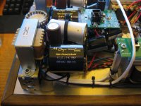
Have you seen a Russian FT3 .1uf? ...its the big silver one 🙂
Attachments
- Status
- Not open for further replies.
- Home
- Loudspeakers
- Multi-Way
- Polarity of the capacitors Auricap