The PMC TB2Si
For about 10 years now I have owned and used a pair of PMC TB2i's. Up till about 5 years ago I used them for monitoring during location recordings. Since then I have used them in my home office, just for listening to music and the incidental job post processing an audio recording.
My reasons for starting this series of posts are:
Given that the TB2 is a really interesting design, and has clearly become a "classic" speaker, not much information (both historical and technical) is available online. I will try to collect whatever I can find, but would greatly appreciate any information you might have. In particular:
The TB2xx are all based on the same design, a two way small transmissionline speaker. There are home hifi versions (TB2, TB2+, TB2i), Professional Monitor versions (Tb2S, TB2Si) and active professional monitor versions (TB2SA, two amplifier versions). As far a I know they all use the same set of drivers.

The port is situated at the back of the speaker and is damped with a piece of foam about 3-4 cm thick, an unusual construction for a TL.

TB2i specs:
Sensitivity: 90dB 1W 1m
Effective ATL™ Length: 1.5m 4.92ft
Impedance: 8 Ohm nominal
Crossover Frequency: 3kHz
Dimensions: H 400mm 15.75″ W 200mm 7.87″ D 300mm 11.81″
Input Connectors: 2 Pairs 4mm Sockets (Bi-Wire or Bi-Amp)
Drive Units:
LF Doped 170mm alloy chassis
HF 27mm, Silk soft dome, Ferrofluid cooled
The history of the PMC TB2
It is surprisingly hard to find any information about the timeline of the introduction of the various TB2 versions. The TB1 and TB2 (original version) were introduced "ïn the 90's". The TB2S (Studio monitor version) around 2000, around the same time as the TB2+ (with the soft dome tweeter).
Vifa D27TG-35-06


The Vifa tweeter is still available for about €40,- in Europe.
Vifa M17WG09-08 (Out of production, only available as NOS)


I do not know if the drivers used in the TB2 are stock Vifa drivers or custom / modified drivers specifically for PCM.
Cabinet
The cabinet is made from 19mm multiplex. The dividers are also multiplex, 9mm thick.
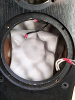
View with both drivers removed. (left) and through the tweeter mounting hole (mid). The top of the first divider is clearly visible here. The line is damped along its entire lenght with the white foam (thickness 50mm). Directly behind the woofer is an extra piece of 25mm thick foam that is actually compressed bij the driver magnet and covers the backside of the driver. This might have consequences for the driver Qt.


The view through the mounting hole of the connectors on the back of the speaker. Visible is the bottom of the second (and last) divider. The picture right shows the port at the back of the speaker and the foam plug in a bad state.


The crossover
The crossover is mounted at the back of the connector panel.


For about 10 years now I have owned and used a pair of PMC TB2i's. Up till about 5 years ago I used them for monitoring during location recordings. Since then I have used them in my home office, just for listening to music and the incidental job post processing an audio recording.
My reasons for starting this series of posts are:
- The foam in the mouth of the line at the back of the TB2's deteriorates over the years. Mine are now basically reduced to dust and need to be replaced. The official replacement foam from PMC is hugely expensive, and I have been looking for an alternative.
- The design of the TB2 has intrigued me for a long tine now. It is a complex design and I would like to find out what makes these speakers what they are.
- Maybe experiment a bit with the crossover.
Given that the TB2 is a really interesting design, and has clearly become a "classic" speaker, not much information (both historical and technical) is available online. I will try to collect whatever I can find, but would greatly appreciate any information you might have. In particular:
- Information about the drivers (stock of custom?)
- Crossover schematics for the various versions.
- Photos or other information about the damping (material, placement).
- Alternatives for the foam plug at the back.
The TB2xx are all based on the same design, a two way small transmissionline speaker. There are home hifi versions (TB2, TB2+, TB2i), Professional Monitor versions (Tb2S, TB2Si) and active professional monitor versions (TB2SA, two amplifier versions). As far a I know they all use the same set of drivers.
The port is situated at the back of the speaker and is damped with a piece of foam about 3-4 cm thick, an unusual construction for a TL.
TB2i specs:
Sensitivity: 90dB 1W 1m
Effective ATL™ Length: 1.5m 4.92ft
Impedance: 8 Ohm nominal
Crossover Frequency: 3kHz
Dimensions: H 400mm 15.75″ W 200mm 7.87″ D 300mm 11.81″
Input Connectors: 2 Pairs 4mm Sockets (Bi-Wire or Bi-Amp)
Drive Units:
LF Doped 170mm alloy chassis
HF 27mm, Silk soft dome, Ferrofluid cooled
The history of the PMC TB2
It is surprisingly hard to find any information about the timeline of the introduction of the various TB2 versions. The TB1 and TB2 (original version) were introduced "ïn the 90's". The TB2S (Studio monitor version) around 2000, around the same time as the TB2+ (with the soft dome tweeter).
| Model | Tweeter part nr. | Tweeter model | Woofer part nr. | Woofer model | Remarks |
| TB1 | 12415 | Vifa D25AG-05-06 | 12418 * | Precursor of the TB2 | |
| TB2 | 12415 | Vifa D25AG-05-06 | 12418 * | ||
| TB2+ | 12416 | Vifa D27TG-35-06 | 12418 | Vifa M17WG09-08 - german type designation 17WN125 | Peerless M17WG09-08 loudspeaker database Crossover freq. 3Khz. Different part nr.? |
| TB2i | 13999 | Vifa D27TG-35-06 | 12418 | Crossover freq. 2Khz | |
| TB2i Signature | 13999 | Vifa D27TG-35-06 | 12418 | Special edition, identical to the TB2i | |
| TB2S | 12415 | Vifa D25AG-05-06 | 12418 * | Professional Monitor, 2001. Review SOS | |
| TB2S-All | 12415 | Vifa D27TG-35-06 | 12418 | Professional Monitor, Active with passive Xover. Review SOS | |
| TB2S-All 5.1 Surround System | 12415 | Vifa D27TG-35-06 | 12418 | Includes the TB2M Center model | |
| TB2S+ | 12415 | 12418 | Professional Monitor |
Vifa D27TG-35-06
The Vifa tweeter is still available for about €40,- in Europe.
Vifa M17WG09-08 (Out of production, only available as NOS)
I do not know if the drivers used in the TB2 are stock Vifa drivers or custom / modified drivers specifically for PCM.
Cabinet
The cabinet is made from 19mm multiplex. The dividers are also multiplex, 9mm thick.
View with both drivers removed. (left) and through the tweeter mounting hole (mid). The top of the first divider is clearly visible here. The line is damped along its entire lenght with the white foam (thickness 50mm). Directly behind the woofer is an extra piece of 25mm thick foam that is actually compressed bij the driver magnet and covers the backside of the driver. This might have consequences for the driver Qt.
The view through the mounting hole of the connectors on the back of the speaker. Visible is the bottom of the second (and last) divider. The picture right shows the port at the back of the speaker and the foam plug in a bad state.
The crossover
The crossover is mounted at the back of the connector panel.
Attachments
The design of the TB2 has intrigued me for a long tine now. It is a complex design and I would like to find out what makes these speakers what they are.
Do you intend to take some measurements (with a mic) and show the dimensions of the internal geometry?
