Hello to everybody.
My Electrocompaniet ECI-4 has been apart for months now.
I finally decided to buy some equipment (scope , good multimeter, variac...) 'cause i'm doing other things too...and therefore i would like to fix this poor amp.
The problem was that a channel blew up.
Now i don't know...maybe it could be that i'm scared to go up with the power supply voltage...but also the other channel seems to not propertly work.
I have checked and re-checked all the semiconductors and they all seem to be fine to me.
The drivers are:
2sa1358-Y (i'm using 1358 O)
2sc3421-Y (i'm using 1358 O)
phase splitter
BD679 ( i have the BD 679A and BD680A which they are different only on the VCEsat 2.8 agains the 2.5V of the 679)
power transistor
2SA1358
2SC5200
(i don't know....just guessing...could it be a contarefed - not genuaine- devices?)
This is a DC coupled amplifier, with a OP amp as a feedback to control the DC at the output.
Output stage in Push-Pull configuration.
Every semiconductor seem to be allright....but when i slowly power the amp up, voltage on the BE-junctions go higer than the maximum rating and therefore of the original project.
I have simulated the circuit with PSpice to have a main view of the problem some reference values to keep the eyes on.
I tried to take the output transistor and phasae splitter off the board re-simulate the new circuit.
On this case, i got the right results compared with the simulation.
I have read around on the forum and on the net that, a usefull trick would be to plug in serie with the main inlet a light bulb to limitate the current (i was actually thinking of a 3 ohm resistor.....but the light bulb is a very cool)
How can i isolate the problem?
Is it possible that the amplifier for low values of power supply voltage could fail?
Using a variable ramp generator as power supply on the simulation, i have noticed that the current on the output devices rises a lot for a certain value of the power supply.
If i'm not understanding wrong, that would't be a problem on a normal condition where the power supply rises up fastly
I don't knonw i'm just trying to interpretate the situation.
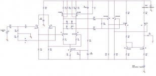
I'm going to attach the complete schematic...maybe can be usefull.
What do you guys suggest me to do after having checked all the semiconductors and capacitors?
Do you guys suggest me to plug just the pre part and not supply the output stage and see what i get out of the pre-section (checking with the scope and signal generator at the input)?
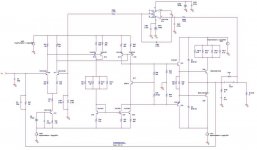
here is the pre stage...
Hope to receive good advice.
Thanks in advance.
Best,
Stefano.
My Electrocompaniet ECI-4 has been apart for months now.
I finally decided to buy some equipment (scope , good multimeter, variac...) 'cause i'm doing other things too...and therefore i would like to fix this poor amp.
The problem was that a channel blew up.
Now i don't know...maybe it could be that i'm scared to go up with the power supply voltage...but also the other channel seems to not propertly work.
I have checked and re-checked all the semiconductors and they all seem to be fine to me.
The drivers are:
2sa1358-Y (i'm using 1358 O)
2sc3421-Y (i'm using 1358 O)
phase splitter
BD679 ( i have the BD 679A and BD680A which they are different only on the VCEsat 2.8 agains the 2.5V of the 679)
power transistor
2SA1358
2SC5200
(i don't know....just guessing...could it be a contarefed - not genuaine- devices?)
This is a DC coupled amplifier, with a OP amp as a feedback to control the DC at the output.
Output stage in Push-Pull configuration.
Every semiconductor seem to be allright....but when i slowly power the amp up, voltage on the BE-junctions go higer than the maximum rating and therefore of the original project.
I have simulated the circuit with PSpice to have a main view of the problem some reference values to keep the eyes on.
I tried to take the output transistor and phasae splitter off the board re-simulate the new circuit.
On this case, i got the right results compared with the simulation.
I have read around on the forum and on the net that, a usefull trick would be to plug in serie with the main inlet a light bulb to limitate the current (i was actually thinking of a 3 ohm resistor.....but the light bulb is a very cool)
How can i isolate the problem?
Is it possible that the amplifier for low values of power supply voltage could fail?
Using a variable ramp generator as power supply on the simulation, i have noticed that the current on the output devices rises a lot for a certain value of the power supply.
If i'm not understanding wrong, that would't be a problem on a normal condition where the power supply rises up fastly
I don't knonw i'm just trying to interpretate the situation.
I'm going to attach the complete schematic...maybe can be usefull.
What do you guys suggest me to do after having checked all the semiconductors and capacitors?
Do you guys suggest me to plug just the pre part and not supply the output stage and see what i get out of the pre-section (checking with the scope and signal generator at the input)?
here is the pre stage...
Hope to receive good advice.
Thanks in advance.
Best,
Stefano.
Attachments

- Status
- Not open for further replies.