These transformers were copies of the Williamson design. 43% UL Tap and the input impedance to suit the output valves.
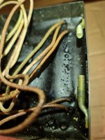
Rubbish. They are for a solid state amplifier, and they don't even have a primary, let alone a UL tap of any description or specification. Look at the picture. It is an autoformer, with the input on the grey lead, on what looks like a 2ohm tap, and various other ohmic tappings available as outputs.
And McIntosh didn't build UL amplifiers. They coupled the screen to the opposite anode, and used a 50% cathode winding. Williamson had nothing to do with it.
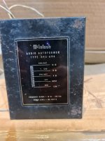
The wiring is specified on the first picture. If the colours are indistinct after all these years, a DVM will tell which windings are which.
And McIntosh didn't build UL amplifiers. They coupled the screen to the opposite anode, and used a 50% cathode winding. Williamson had nothing to do with it.
The wiring is specified on the first picture. If the colours are indistinct after all these years, a DVM will tell which windings are which.
Last edited:

Thanks
Just my guess. Correct me if i am wrong.
Say the amp is design with 8ohm spk and connected to input of the autoformer. Whats the other tap become? 4x of original value?
Whats the use case of the autoformer? For impedance matching?Rubbish. They are for a solid state amplifier, and they don't even have a primary, let alone a UL tap of any description or specification. Look at the picture. It is an autoformer, with the input on the grey lead, on what looks like a 2ohm tap, and various other ohmic tappings available as outputs.
And McIntosh didn't build UL amplifiers. They coupled the screen to the opposite anode, and used a 50% cathode winding. Williamson had nothing to do with it.
The wiring is specified on the first picture. If the colours are indistinct after all these years, a DVM will tell which windings are which.
Just my guess. Correct me if i am wrong.
Say the amp is design with 8ohm spk and connected to input of the autoformer. Whats the other tap become? 4x of original value?
Yes it is for impedance matching to the speaker. The other taps behave as marked.
And BTW the Williamson design is not UL.
And BTW the Williamson design is not UL.
Last edited:
At the time (even now), the SOA of a BJT transistor strongly favors lower voltage and (for a specified power) higher current.Whats the use case of the autoformer? For impedance matching?
Most designers let the transistors strain, or go to stacked devices. And power varies with impedance.
This (quite old) Mac plan designed the transistors for something like a 2.5 Ohm load (depending on power level) and then a 2.5/4/8/16 autotransformer to suit the user's speakers.
While transformers have a bad reputation, high-impedance (tube) drive is worst, low-Z drive swamps the stray capacitance. Stray inductance matters, but Mac had done really-really well winding wideband transformers. Weight and cost are still a problem, except Mac makes a heavy costly product a selling-point.