Hi All,
Recently I cleaned up the attic and found a project I never finished. With autumn almost here I searched for a schematic that fits the parts and Yves' design is a close match.
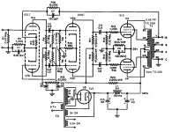
In short I wanted to build the schematic I found from Yves 6l6 PP but without the fixed bias potentiometers.

I've been searching on cathode bias, and found some information but I'm not sure how to apply it and if it is even possible...
If possible could you help me understand how to change the schematic to cathode bias and provide with the steps necessary to do so.
Or a link to another website or thread if I missed that would also be great.
thank you for your time in advance.
Recently I cleaned up the attic and found a project I never finished. With autumn almost here I searched for a schematic that fits the parts and Yves' design is a close match.
In short I wanted to build the schematic I found from Yves 6l6 PP but without the fixed bias potentiometers.
I've been searching on cathode bias, and found some information but I'm not sure how to apply it and if it is even possible...
If possible could you help me understand how to change the schematic to cathode bias and provide with the steps necessary to do so.
Or a link to another website or thread if I missed that would also be great.
thank you for your time in advance.
You're right, that's probably something I should have mentioned in my 1st post.
Well I have never owned/build an amp that needed the bias to be set manually. I like the building part, but when it's build I just want it to work. From experience I know a tube amp needs some more maintenance then a regular of the shelf amp. But I really like to keep it to a minimum.
From what I've read some amps need to be corrected every week, some once a year. So I thought it would be an option to investigate if cathode bias would be possible.
That said, there is probably a good reason Yves choose to use fixed bias over cathode bias. But I lack the knowledge to judge that.
Biasing a fixed bias valve amp is not that much of a problem. Probably every few months with heavy use - as in a gigging guitar amplifier, or maybe every year with light use - as in a home hi-fi amplifier.
Cathode bias amps are often favoured by guitarists because of their sustain and overdrive characteristics.
Fixed bias is associated with more powerful, more efficient ampifiers and is arguably the better choice for hi-fi use.
Cathode bias amps are often favoured by guitarists because of their sustain and overdrive characteristics.
Fixed bias is associated with more powerful, more efficient ampifiers and is arguably the better choice for hi-fi use.
Your amplifier is way too complex for cathode bias, which on the contrary shines in **simple** amplifiers, emphasis on simple.
If you have just a pentode (on triode) DC isolated from anything else (hint: coupling caps), then each one works on its own. Now when 2 tubes share a common cathode resistor problems start to arise, since one may hog current away from the other if mismatched.
Now build a 4 tube DC coupled stage and the potential for mismatching problems becomes huge ... hence the individual trimmers in yours. They are there for a good reason 🙂
Seriously, not sucg a big deal. And if others said this amp requires frequent biasing, now you know why, it´s in its genes.
Just thinking aloud, I am certain some clever guy may design some kind of servo bias which keeps everything steady, it´s Technically quite possible ... only problem is to find him.
Never dug deeply into that, but AMPEG SVT Bass amplifiers lately added some kind of intelligent self bias, maybe you should search for that schematic and see whether you can adapt it to your needs.
If you have just a pentode (on triode) DC isolated from anything else (hint: coupling caps), then each one works on its own. Now when 2 tubes share a common cathode resistor problems start to arise, since one may hog current away from the other if mismatched.
Now build a 4 tube DC coupled stage and the potential for mismatching problems becomes huge ... hence the individual trimmers in yours. They are there for a good reason 🙂
Then pick another project 🙂I have never owned/build an amp that needed the bias to be set manually.
Seriously, not sucg a big deal. And if others said this amp requires frequent biasing, now you know why, it´s in its genes.
Just thinking aloud, I am certain some clever guy may design some kind of servo bias which keeps everything steady, it´s Technically quite possible ... only problem is to find him.
Never dug deeply into that, but AMPEG SVT Bass amplifiers lately added some kind of intelligent self bias, maybe you should search for that schematic and see whether you can adapt it to your needs.
Indeed, it's already been achieved, this "servo biasing".
David Gillespie has implimented his "ESB" system of biasing, and I've used it with excellent results.
Basically, it's used with a fixed biased amp, with an LM337 negative adjustable regulator controlling the output cathodes in a type of "constant current" arrangement.
This regulator takes its control during operation from the power supply itself, tracking the up-down B+ voltage lagging caused by heavy transients, and instantly keeping the output bias "in step" and basically ideal.
This greatly improves things by eliminating the possibility of control grids being driven into saturation, and allows the tubes to produce even more wattage cleanly.
My ultralinear PP EL84 amp, built using a Magnavox 9204 chassis is proof of this - before, with classic cathode bias, it used to clip/distort at a higher volume level, which got annoying occasionally.
With the "EFB" system, it now is clean and stable past that same loud volume level, and actually cranks out a couple more watts (17+) than before.
The bottom line is, you get the "higher power" that fixed bias promises, but with no biasing deviations.
Last edited:
My tube amp originally had a paraphase splitter, and it was just ok. However once I rebuilt the amp with a concertina, it made a world of difference and sparkle. Now, I did all my amps that way and never look back.This is an easier amp for a beginner to build. Cathode bias (but I would use separate R's and C's on the 6l6 cathodes to avoid current "hogging.")
Since you already have all the parts, I would just build the circuit as the schematic you posted. Just put is two fix 560R resistor in place of R6 and R21 trim pots. That is the most simple way and properly the best way.I've been searching on cathode bias, and found some information but I'm not sure how to apply it and if it is even possible...
If possible could you help me understand how to change the schematic to cathode bias and provide with the steps necessary to do so.
If you must convert the 6L6 to cathode bias one simple way to do that is to add two .22uf 400V+ capacitor between R8, R22 and the cathodes of V1b and V2b. This will DC decouple the cathode follower driver which also set the 6L6 bias. You will need to put in two grid leak resistors of about 220K or so on the 6L6 grid. Next you will need to put in the two 6L6 bias resistor in place of the 10 ohms R9 and R23. If you set the bias to about 22V and 40ma, you will need a 22/.04 or 550 ohms, 2-3W. You will also need two cathode by pass caps. 200-500uF should do the job.
Grid leak resistor are put between grid to ground. Cathode bypass cap are parallel to cathode resistors.
Last edited:
Thank you all for your reply’s. It gives me lots to think about 🙂
Ok so just build it. I could be looking into a way of conveniently set the bias. With some nice analog ammeter. But I don't really like to have 4. So I'll have a search on the forum, there's probably some more people that thought and discussed this.
Thanks for sharing a schematic, but I choose the 1st posted schematic:
-Because it has documented test results.
-It is for all 6L6-oids even the older ones that don't like high screen grid voltage.
-Also I have 6k OPTs (50watt) not 6k6 OPTs. (I looked at the original 6L6 datasheet, It showed an option for AB2 using the 6K OPT, but I am nowhere qualified enough to design a schematic with these parameters and couldn’t find one matching the 6K OPT.
-I do have a lot of other tubes like 6SN7’s 6SL7’s, so if I find a documented schematic that would match the components I have… even more to think about... but let's not do that for now.
Ah that was my first guess treat the POT as a parallel resistor. but I didn’t think it could be so simple. And I didn't know what value to calculate with. So in my calculation I used 500R to calculate the resistor and replace it with 264R then add R5 390R gives me 654R so say replace R5, R6 & R7 with 680R
Could I do the same with the R16 470R pot? Just split it in half and settle for 220R or 240R?
Ok that’s sounds rather easy. I will think about this some more while drawing your suggestions.
Your are right. I’m being to hesitant. But it is good to know I could convert the amp if I ever feel the need.
Fixed bias is associated with more powerful, more efficient ampifiers and is arguably the better choice for hi-fi use.
hence the individual trimmers in yours. They are there for a good reason 🙂 Then pick another project 🙂
Ok so just build it. I could be looking into a way of conveniently set the bias. With some nice analog ammeter. But I don't really like to have 4. So I'll have a search on the forum, there's probably some more people that thought and discussed this.
This is an easier amp for a beginner to build. Cathode bias (but I would use separate R's and C's on the 6l6 cathodes to avoid current "hogging.")
Thanks for sharing a schematic, but I choose the 1st posted schematic:
-Because it has documented test results.
-It is for all 6L6-oids even the older ones that don't like high screen grid voltage.
-Also I have 6k OPTs (50watt) not 6k6 OPTs. (I looked at the original 6L6 datasheet, It showed an option for AB2 using the 6K OPT, but I am nowhere qualified enough to design a schematic with these parameters and couldn’t find one matching the 6K OPT.
-I do have a lot of other tubes like 6SN7’s 6SL7’s, so if I find a documented schematic that would match the components I have… even more to think about... but let's not do that for now.
Just put is two fix 560R resistor in place of R6 and R21 trim pots. That is the most simple way and properly the best way.
Ah that was my first guess treat the POT as a parallel resistor. but I didn’t think it could be so simple. And I didn't know what value to calculate with. So in my calculation I used 500R to calculate the resistor and replace it with 264R then add R5 390R gives me 654R so say replace R5, R6 & R7 with 680R
Could I do the same with the R16 470R pot? Just split it in half and settle for 220R or 240R?
If you must convert the 6L6 to cathode bias one simple way to do that is to add two .22uf 400V+ capacitor between R8, R22 and the cathodes of V1b and V2b. This will DC decouple the cathode follower driver which also set the 6L6 bias. You will need to put in two grid leak resistors of about 220K or so on the 6L6 grid. Next you will need to put in the two 6L6 bias resistor in place of the 10 ohms R9 and R23. If you set the bias to about 22V and 40ma, you will need a 22/.04 or 550 ohms, 2-3W. You will also need two cathode by pass caps. 200-500uF should do the job.
Grid leak resistor are put between grid to ground. Cathode bypass cap are parallel to cathode resistors.
Ok that’s sounds rather easy. I will think about this some more while drawing your suggestions.
Since you already have all the parts, I would just build the circuit as the schematic you posted.
Your are right. I’m being to hesitant. But it is good to know I could convert the amp if I ever feel the need.
It is not simple but either it is complicated. Step one is to calculate the output 6L6GC bias point. Search for a 6L6GC data sheet. Look for a Ip vs Vp (plate/anode to cathode) chart. The design you want call for Vp of about 400V and an Ip of 40ma with a G2 voltage of about 272V. If you do some reading you will find for that bias point Vg (Grid to Cathod) should fall a bit more negative than -22V. Lets use 22V as the Vg bias for now since a bit more Ip (but not too much more) is a good thing.Ah that was my first guess treat the POT as a parallel resistor. but I didn’t think it could be so simple. And I didn't know what value to calculate with. So in my calculation I used 500R to calculate the resistor and replace it with 264R then add R5 390R gives me 654R so say replace R5, R6 & R7 with 680R
Could I do the same with the R16 470R pot? Just split it in half and settle for 220R or 240R?
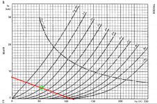
The voltage drop between R3+R5+(R7//R6) should be around -115 - (-22V) or -93V. R(total) should be = -93/8mA (per schematic) or ~11.6K. If you look at ECF80 data sheet and the triode curve. A good Vg bias for 8mA could be -2V. so R5+(R7//R6) = -2/8mA = ~250 ohms. And R3 should be 11.6K - 250hms or ~11.35K. Notice R3 is less than the 12K value in the schematic and all the resistors needed are odd ball value. May be this is why you have problem in the first place. The way way to bring up this amp is to have some number resistors at hand and adjust the value as you measure and bring up B+.
R16 is not used to adjust output tube bias, it is what is call AC balance. It effects the out harmonic distortion. If you don't care to tune this (have the ears or equipment) use two 230R resistor.
Thanks for your explanation! I have a bit more questions now but first let's see if I followed your suggestions correctly.
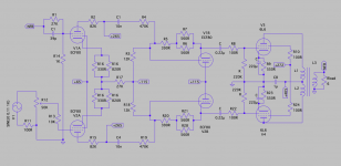
So I started with drawing you suggestions. It is attached to this post.
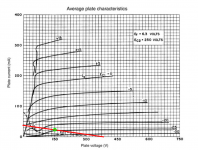
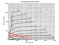
I assume you mean the “average plate characteristics” chart? I could only find charts that show Ec2 (screen grid?) as 250V. When I draw a line from 40mA to 400V the center touches around -25. Is this correct?
Also attached. This raises no questions because when I draw the line it is spot on at -2V.
It is not simple but either it is complicated.
So I started with drawing you suggestions. It is attached to this post.
Search for a 6L6GC data sheet. Look for a Ip vs Vp (plate/anode to cathode) chart. The design you want call for Vp of about 400V and an Ip of 40ma with a G2 voltage of about 272V. If you do some reading you will find for that bias point Vg (Grid to Cathod) should fall a bit more negative than -22V. Lets use 22V as the Vg bias for now since a bit more Ip (but not too much more) is a good thing.
I assume you mean the “average plate characteristics” chart? I could only find charts that show Ec2 (screen grid?) as 250V. When I draw a line from 40mA to 400V the center touches around -25. Is this correct?
The voltage drop between R3+R5+(R7//R6) should be around -115 - (-22V) or -93V. R(total) should be = -93/8mA (per schematic) or ~11.6K. If you look at ECF80 data sheet and the triode curve. A good Vg bias for 8mA could be -2V. so R5+(R7//R6) = -2/8mA = ~250 ohms. And R3 should be 11.6K - 250hms or ~11.35K.
Also attached. This raises no questions because when I draw the line it is spot on at -2V.
Attachments
It seems I cannot edit messages after 30 minutes.
I assume you mean the “average plate characteristics” chart? I could only find charts that show Ec2 (screen grid?) as 250V. When I draw a line from 40mA to 400V the center touches around -25. Is this correct? Or is 40mA the midpoint and should I draw the line from 80mA to 400V
I assume you mean the “average plate characteristics” chart? I could only find charts that show Ec2 (screen grid?) as 250V. When I draw a line from 40mA to 400V the center touches around -25. Is this correct? Or is 40mA the midpoint and should I draw the line from 80mA to 400V
Attachments
Last edited:
Is that last circuit correct C1/C4 should be connected to anode not supply?
I numbered incorrectly it should be C2 and C4. I followed the original schematic and applied the suggestions. In the original schematic they are connected to the grid. R4 & R19 are wrong. and I forgot C3 from the original schematic. I'll try to redraw it again tomorrow.
Note to self, don't start drawing if you don't have the time....
Last edited:
Sorry the schematic, I cannot see any signal path from v1a to v1b or am I seeing double. Sorry think you have pointed out the error.
You have the correct V/I curve for 6L6. One correct way to draw a load line is to draw a line from 400V to 133mA. This is a 3K load line (each 6L6 see half of the 6K output transformer). The133mA value came from 400V/3K. Once your draw that line, move that line up vertically by 40mA (your planned bias). Move the lower point to 40mA, upper point of the line to 133+40mA=173mA. Now extend the lower end of the line to 0 mA following the same line slop. This line now represent the AC loading that each 6L6 will see with a 6 ohms resistive output load when the amp is in class A.It seems I cannot edit messages after 30 minutes.
I assume you mean the “average plate characteristics” chart? I could only find charts that show Ec2 (screen grid?) as 250V. When I draw a line from 40mA to 400V the center touches around -25. Is this correct? Or is 40mA the midpoint and should I draw the line from 80mA to 400V
The bias point is the intersection of 40mA and 400V on the load line. Grid voltage should be near -22V.
Last edited:
Also G2 for your curve is for 250V. At 272V, your planned G2 Voltage, Plate current Ip should be higher for any given grid voltage. Since 272V is less than 10% higher than 250V, the difference in Ip should only a little more. A little higher idle Ip typically yield lower distortion. I would leave it as is rather than redrawing a new curve or gusstimate a new bias point for G2 = 272V.
Yes, C2, C4 and R2 and R15 are connected wrong on new schematic. C3 is also deleted in new schematic.
- Status
- Not open for further replies.
- Home
- Amplifiers
- Tubes / Valves
- please help me walk through the steps to convert to cathode auto bias