Hello. I picked up my first LOMC cartridge and tried to build the common-base circuit head amp shown here
I also used this as an excuse to take my first steps in designing PCBs using Eagle. I *think* the attached files accurately reflect the circuit on the website (Gerber files).
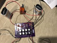
I tried running a reference tone through the head amp and only got an input voltage of 2.8 mV and an output voltage of 5.9 mV on the right channel. The left channel was similar but a bit lower. I have attached a photo of my actual circuit. The circuit is supposed to have a voltage gain of 20 (26 dB), so I'm thinking I did something wrong, but I'm not sure where to start. One thing I did see is that the resistor value R2 needs to be selected so the battery current is 0.125 mA. I have a meter but I'm not sure where I should measure to get this value.
Any suggestions are much appreciated. Thank you!
I also used this as an excuse to take my first steps in designing PCBs using Eagle. I *think* the attached files accurately reflect the circuit on the website (Gerber files).
I tried running a reference tone through the head amp and only got an input voltage of 2.8 mV and an output voltage of 5.9 mV on the right channel. The left channel was similar but a bit lower. I have attached a photo of my actual circuit. The circuit is supposed to have a voltage gain of 20 (26 dB), so I'm thinking I did something wrong, but I'm not sure where to start. One thing I did see is that the resistor value R2 needs to be selected so the battery current is 0.125 mA. I have a meter but I'm not sure where I should measure to get this value.
Any suggestions are much appreciated. Thank you!
Attachments
I built this circuit quite some time ago; the gain is very sensitive to the value of R2. Since the current flowing in the divider is only about 20 microamps, it is probably easiest to just connect your meter in series with the battery. If you want more gain, use a higher current, say double.
Is there a circuit diagram ?
Hello and thanks for looking at my post. I realized on issue late last night is that the pin-out for Q1 on my board is ECB but the transistor is EBC. I need to pull those two out and resolder with the leads in the correct holes.
I resoldered the NPN transistors with the leads in the correct holes and now get a 12.8 dB gain. I also jumpered the power from the Left channel to supply the right (no both are running off of 1 9V battery), since I realized that the difference in gain in L and R channels was because of the two different batteries. In practice, the transistors seem very noisy and equal on both sides. I'm guessing there's just not enough gain to get a good signal:noise ratio. I'm going to wire another 9V battery in, so both channels are wired in parallel with the 2 9V in series.
As far as grounding my turntable goes, can I just connect the groundwire to one of the ground connections on the RCA inputs? The original circuit has the chassis ground as one of the capacitors, but the RCA is acting as the chassis ground if I don't insulate the connector from the enclosure (I think?). Any advice is appreciated!
As far as grounding my turntable goes, can I just connect the groundwire to one of the ground connections on the RCA inputs? The original circuit has the chassis ground as one of the capacitors, but the RCA is acting as the chassis ground if I don't insulate the connector from the enclosure (I think?). Any advice is appreciated!
Last edited:
- Status
- Not open for further replies.