Hi there,
I built this simple guitar preamp. I have inductors in the circuit. I've simulated the circuit and simulated the power with a pulse. I've had to replace 4 or 5 inductors during the build. After they fail, I test the inductor by measuring its dc resistance with a multimeter and they have very high resistance. The normal resistance is about 240 ohms. Anyhow, their rated at 15ma, and when I do simulations with a pulse I'm getting about 7ma.
I'm thinking the current must transiently peak to high to burn them out. But the preamp sounds fine when on (as long as an inductor hasn't died).
Any help or suggestions please!
Thanks
Attachments
Actually, I'm able to get pulses of 14ma for certain settings, and lowering the intrinsic dc resistance of the inductor a little in the simulation. So I'm going to add a series resistor maybe 470 ohm or so to see if this helps.
The circuit looks like it shouldn't take much current so I would suggest they are getting damaged when being soldered in. Too much heat is making the internal wires come undone ?
Current burnout is from heat, do the iductors look over heated? (Discolored) might be to much voltage punching holes in the insulation. ( stopping current in an inductor will spike the voltage across it ) what doe spice show for inductor voltage?
Ok thanks guys, I was wondering about maybe getting them too hot soldering I was using a 30watt gun. There is no visible damage to the inductors, but they would go from 240 ohms dc resistance to very high resistance (using old needle style multimeter which didn't move). But I did run a 9 volt pulse wave as a voltage source and their peaking right at about 15ma. So I'm not sure if a transient voltage spike would kill the inductor. These are small radial 38 cent RF inductors I believe are probably not intended for audio (300 ohm max, 15ma max). So I the preamp is now working, and I put a 470 ohm inductor in series with the inductors in the Mid controls. I had already put 1k resistors in series with the Bass controls, because it sounded better, and come to think of it, they haven't failed yet. So now all I have to do is turn it on and off 100xs and see what happens. Thanks everyone. I'll repost later after I've used it for awhile to see how stable it seems.
Maybe you need to improve your soldering technique? A 30W gun is a bit too big for these, but used properly they ought to survive. I would use something more like 20-25W soldering iron. Perhaps use proper leaded solder instead of this modern awful 'safe' stuff?
Maybe you need to improve your soldering technique? A 30W gun is a bit too big for these, but used properly they ought to survive. I would use something more like 20-25W soldering iron. Perhaps use proper leaded solder instead of this modern awful 'safe' stuff?
And use alligator clips on the inductor leads - nearest to the inductor
It must be a soldering issue. I directly hooked up a 9 volt battery several times to the inductor for about 30 seconds and it did not die. So it appears to not be a voltage spike issue. I will be more careful soldering and lower the temp/wattage/soldering time and see what happens. And I agree with the soldering comments from KMossman. The melting point for the lead-free solder is higher and this along with technique probably killed the inductors. I think your correct JMFahey.
The inductor is rated for 14mA max, a 9V battery with 240R will deliver 37.5mA. The wire size used in those is very small and is fragile.
Does this happen at all positions of the tone pots?
It is possible for some resonant circuits to put out more current than a simple sim will show you, a capacitor discharging through an inductor can generate quite a lot of current - which is probably why the damping resistor fixed the issue.
You should simulate it it with some AC conditions at the edge of the circuit's capabilities - and a bit beyond - to see what is happening. If this is a guitar preamp, maybe 10x the expected signal input and some nasty square waves (from some distortion pedals), you will be able to see the actual current through the components.
My apologies if you've already done this.
Yes i knew the 9volt hooked up to the inductor would exceed the current rating i was basically trying to exceed the current rating purposefully and they didnt fail. So my reasoning was if they transiently hit 15 ma or so their probably not dying if i can run 37.5 ma continuously. I was simulating a guitar signal as a sine wave .18mv 10k series resistance. Im going to try a square wave 1volt amplitude and see what happens with the simulation. Im also going to try shifting the phase so at time zero the amplitude is at maximum before caps have charged to see what current is going through them. Ill step the tone controls from 0 to max and look for current/voltage spikes across the inductors.
I put the input voltage up on the input to 1 volt amplitude and looked at the bode plot to find out where maximum currents peak at, then I simulated at those frequencies and was able to get 15ma positive peak and -10ma negative peak. What I'm going to do next is get rid of the inductor based bass control in the circuit and put a bass control in series to the input. I will put a .0033uf capacitor on the input with a 1MEg pot parallel to it like what they did in the two tone G and L 2 tone guitar mod and get rid of 1 inductor. I'm going to make sure there's a damping resistor on the midrange control. I'm going to build it on a nonsolder prototype board and use it that way for a while and see if it does ok. Then I will try soldering it. I also will use a lower wattage gun to solder and use that alligator clip trick. I think this will probably work ok.
You could also try through-hole ferrite inductors. A 1/2 watt unit can take whatever you want to throw at it. They look exactly like resistors, and have similar colour codes but in uH base.
Thanks
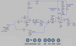
I build the following similar circuit on a solderless prototype board, and so far it seems to work ok. I used 2 inductors in series for 200mh and the 470 ohms represents the intrinsic series resistance of both. I did this because it gives a narrower bandwidth on the notch filter and approximates a marshall tone stack better. So far it seems to work fine. After I build for real I will repost. Thanks everyone for your help.
I build the following similar circuit on a solderless prototype board, and so far it seems to work ok. I used 2 inductors in series for 200mh and the 470 ohms represents the intrinsic series resistance of both. I did this because it gives a narrower bandwidth on the notch filter and approximates a marshall tone stack better. So far it seems to work fine. After I build for real I will repost. Thanks everyone for your help.
Attachments
- Status
- Not open for further replies.
- Home
- Live Sound
- Instruments and Amps
- Please help, inductors keep dying