Hi all
I have been working on the design of the power amp. My decision is to split the OPS from the IPS/VAS. I want to make the pcb as versatile as possible. I want to use the same pcb for OPS and design small front end pcb for different IPS and VAS configurations. So I can try them out cheap.
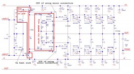
This OPS receives input from the front end board +IN and -IN from the VAS output. The two inputs connect directly to the two Vbe multiplier. In the schematic, the signals on the left side connect to the front end board, the right side are the power input, output and power ground.
I am planning to make the board like 10" X 1.75" so I have room to mount the front end board onto the heat sink. If it does not fit, I can always mount on the bottom of the chassis butt up to the power board.
I made a few options:
1) I want to adapt this board for MOSFET power transistor. So I put in the error correction circuit from Fig.12 page 11 of Mr. Cordell's paper. http://cordellaudio.com/papers/MOSFET_Power_Amp.pdf But I am going to use BJT in my first try. All the components inside the red box labeled "stuff for MOSFET only" will not be stuff. Without stuffing the components in the box, the board is just a 3EF without cutting any trace. For MOSFET, stuff the components and change the power BJT into MOSFET and adjust the resistors of the two Vbe multiplier accordingly. I don't even want to think about it at this point.
2) I still contemplate using darlington for the second pre-driver Q26 and Q27. All I have to do is jumper base to emitter of Q20 and Q21 to bypass the first EF stage. Change Q2 to darlington, adjust the value of the resistors around Q2 for 6Vbe and jumper Q1 away.
I hope I can make one version of pcb to test out different configurations. With the ability of swapping front end boards, I can have a lot of different configurations I can try.
Please comment and thanks for your time
Alan
I have been working on the design of the power amp. My decision is to split the OPS from the IPS/VAS. I want to make the pcb as versatile as possible. I want to use the same pcb for OPS and design small front end pcb for different IPS and VAS configurations. So I can try them out cheap.
This OPS receives input from the front end board +IN and -IN from the VAS output. The two inputs connect directly to the two Vbe multiplier. In the schematic, the signals on the left side connect to the front end board, the right side are the power input, output and power ground.
I am planning to make the board like 10" X 1.75" so I have room to mount the front end board onto the heat sink. If it does not fit, I can always mount on the bottom of the chassis butt up to the power board.
I made a few options:
1) I want to adapt this board for MOSFET power transistor. So I put in the error correction circuit from Fig.12 page 11 of Mr. Cordell's paper. http://cordellaudio.com/papers/MOSFET_Power_Amp.pdf But I am going to use BJT in my first try. All the components inside the red box labeled "stuff for MOSFET only" will not be stuff. Without stuffing the components in the box, the board is just a 3EF without cutting any trace. For MOSFET, stuff the components and change the power BJT into MOSFET and adjust the resistors of the two Vbe multiplier accordingly. I don't even want to think about it at this point.
2) I still contemplate using darlington for the second pre-driver Q26 and Q27. All I have to do is jumper base to emitter of Q20 and Q21 to bypass the first EF stage. Change Q2 to darlington, adjust the value of the resistors around Q2 for 6Vbe and jumper Q1 away.
I hope I can make one version of pcb to test out different configurations. With the ability of swapping front end boards, I can have a lot of different configurations I can try.
Please comment and thanks for your time
Alan
Attachments
Personally, I would allow for some power rail snubbers. Also, maybe add some 1R + 1U power rail filtering between the output transistors and the drivers/pre-drivers. This may be useful when getting stability especially with MOSFETs.
How does the output stage know when it is at centre voltage? How do you think the differential input can work the way you have designed it? There is no pull-up current for Q20/21.
It is supposed to be driven by the IPS and VAS that will be on a separate front end board. As you can see the signal on the left side, the OUT is feeding back to the front end board for global feedback to control the quiescent voltage to 0V.How does the output stage know when it is at centre voltage? How do you think the differential input can work the way you have designed it? There is no pull-up current for Q20/21.
This is going to be a conventional amp, I just separate the OPS from the front end IPS and VAS. So I can layout different IPS and VAS on smaller boards and change as will.
Personally, I would allow for some power rail snubbers. Also, maybe add some 1R + 1U power rail filtering between the output transistors and the drivers/pre-drivers. This may be useful when getting stability especially with MOSFETs.
Good idea. I will add that. What is 1R+1U?
Thanks
I believe, +INPUT and 0.1 poly have to be connected to the base of Q20, not Q1.
Otherwise it will not work...
Otherwise it will not work...
I believe, +INPUT and 0.1 poly have to be connected to the base of Q20, not Q1.
Otherwise it will not work...
Yes, it's an error, I'll correct it.
Thanks
I fixed the error, added the RC in between the power transistors and the pre-drivers. Also, I put diodes in series with resistor to connect between the emitters of the complementary pre-drivers Q26 & Q27, Q20 and Q21. I want to have lower resistance between the emitters to speed up the discharge of the input capacitance of the big BJT. The diodes take up part of the voltage so I can use lower resistance to reduce the time constant.
Attached is the up dated schematic. Please comment.
Thanks
Attached is the up dated schematic. Please comment.
Thanks
Attachments

Last edited:
Attached is the up dated schematic. Please comment.
Thanks
Thermal comment .... you are changing the co-efficient of the vbe with
Q1 (thermally coupled with the predrivers). running at a higher Ic , your
pre-drivers will be very thermally stable.
They don't see much thermal distortion (cycling) , mostly just ambient.
Mostly , the drivers ( with varying output loads) and the output stage itself
needs to be "tracked" in an EF3.
Typically , an EF3 with driver/output pair on the main sink uses 1 thermally coupled
device. Separate driver heatsink , sometimes two Vbe's ... to "fine tune" for different loads.
In any case , once you've built it .... you will have to sit by and physically monitor
it ... re-adjusting passives to match the Ksa-xxxx Vbe to the outputs Vbe.
... Or switch to a MJE .
No easy way to exactly pre-determine (calculate) this.
PS -I just found that a MJE340 (as Vbe) matches Sanken MT-100/200's perfectly but has a slight negative result with ON semi output devices.
OS
Yes, I am counting on Q1, Q20 and Q21 track each other around ambient temperature.Thermal comment .... you are changing the co-efficient of the vbe with
Q1 (thermally coupled with the predrivers). running at a higher Ic , your
pre-drivers will be very thermally stable.
They don't see much thermal distortion (cycling) , mostly just ambient.
Do you mean pre-driver Q26 and Q27 tracking the big BJTs? I have in mind they are on the heat sink with Q2 so Q2 is used to track the temperature of the heatsink.Mostly , the drivers ( with varying output loads) and the output stage itself
needs to be "tracked" in an EF3.
Typically , an EF3 with driver/output pair on the main sink uses 1 thermally coupled
device. Separate driver heatsink , sometimes two Vbe's ... to "fine tune" for different loads.
In any case , once you've built it .... you will have to sit by and physically monitor
it ... re-adjusting passives to match the Ksa-xxxx Vbe to the outputs Vbe.
... Or switch to a MJE .
No easy way to exactly pre-determine (calculate) this.
PS -I just found that a MJE340 (as Vbe) matches Sanken MT-100/200's perfectly but has a slight negative result with ON semi output devices.
OS
Is there a difference in Vbe and temp co between the KSA/KSC vs like MJE or MJW?
BTW, I forgot where your posts on winding the output inductor. I remember you said you wound on an AA battery, how many turns and what gauge insulated copper wire? So many things to think about. I have been searching parts day and night, work harder than a real job!!! Still have the front end IPS and VAS board, power supply board ( maybe) and definitely output relays to protect the speakers. I really need a vacation from my hobby!!!
Thanks
I have a question. I confirmed from Mr. Cordell that the emitter resistor should not be under 0.15ohm. That means the current should not exceed 180mA to conform to Oliver's condition to minimize crossover distortion. 4 stages only give 4 X 180mA = 720mA. This mean I can count on sinking or sourcing 2 X 720mA = 1.44A before going into Class B. That is only 4.14W rms of class A power or 5.76Vpeak before going into Class B.
Should I add more power BJT to get more Class A power? 5 stages will give 5.6W. 6 stages give 7.5W.
Should I add more power BJT to get more Class A power? 5 stages will give 5.6W. 6 stages give 7.5W.
Is there a difference in Vbe and temp co between the KSA/KSC vs like MJE or MJW?
BTW, I forgot where your posts on winding the output inductor. I remember you said you wound on an AA battery, how many turns and what gauge insulated copper wire? So many things to think about. I have been searching parts day and night, work harder than a real job!!! Still have the front end IPS and VAS board, power supply board ( maybe) and definitely output relays to protect the speakers. I really need a vacation from my hobby!!!
Yes , Mje 340 (as vbe) matches mt-100 sankens , ksa3503 matches mjl/njw ON's. At least on the
badger/slewmaster OPS's. I'm leaving the 340 for my ON slew , just a 2mv negative
between 20-50C. A slight tweak of the Vbe divider could fix this .... but , not a real
big issue.
18ga. enameled wire is 16 turns on a AA battery for 1.5uH.
16ga is 18T for the same inductance.
Calculate as you desire - AA battery is .55" ....
Air Core Inductor Coil Inductance Calculator
OS
Thanks. I have second thoughts on the 2SA and 2SC. I am leaning towards MJE15032 and 15033 50W 30MHz beta=70 at 500mA for the 2nd pre-driver. I am really thinking about adding the 5th stage like your amp to get a little more Class A power so I want to beef up the 2nd pre-driver a little.Yes , Mje 340 (as vbe) matches mt-100 sankens , ksa3503 matches mjl/njw ON's. At least on the
badger/slewmaster OPS's. I'm leaving the 340 for my ON slew , just a 2mv negative
between 20-50C. A slight tweak of the Vbe divider could fix this .... but , not a real
big issue.
18ga. enameled wire is 16 turns on a AA battery for 1.5uH.
16ga is 18T for the same inductance.
Calculate as you desire - AA battery is .55" ....
Air Core Inductor Coil Inductance Calculator
OS
I think you guys are right about 40V is a little too low for the rail. I decided to go to 50V to give some headroom for the ripple voltage. So it's not wrong to add one more stage to spread the heat.
Thanks
2 cents on X-over distortion.
On a typical musical signal , HF "rides" on the LF (carrier freq.).
So , if you are listening real low.. HF/LF will never transition to AB.
Conversely , at high levels - HF is "riding" the larger LF wave (drum/bass note.)
HF would only intersect the X-over region at the frequency of the LF signal.
Most of the time HF would be in full conduction on one of the output devices.
An exception to this is where a voice or other high pitch is NOT being modulated
by a bass note (and has the dominant amplitude).
This could be why a class AB CAN sound good , as the X-over "glitch" only
appears on the carrier ( which goes to the woofer - usually).
Right at a certain volume (your 4W) , both your carrier and high freq would be
crossing into AB. No real way to avoid this ... cross your fingers and hope either
your NFB is fast enough to (partially)correct it ... and are in optimal AB bias.
OR - go all the way to full class A.
PS - I've heard a 200W class A (genesis stealth) and a (few) 200W AB's.
Extremely hard to distinguish between them.
In fact -The Harmon/Kardon 990 , the Genesis stealth , and my new 200W'er
sound nearly identical.
BTW , all the AB's have 800 - 1kva PS's... stealth had 2Kva
(for its 10A's of pure class A 😱).
Lesser amps with cheap power supplies - you can hear a difference
I was being told I over killed when I want to buy a 625VA transformer!!! I expect to run a little into Class AB occasionally, that's the reason I am careful in setting the current no more than 200mA with the emitter resistor of 0.15ohm to optimize the crossover distortion.
The sound of my Acurus improve noticeably when I cranked the idle current from 10mA to 100mA even leaving the 0.5ohm emitter resistor unchanged. I even got more 0.5ohm to parallel with the original 0.5ohm, just too lazy to solder in. On paper, my new amp should have much more power in Class A.
The sound of my Acurus improve noticeably when I cranked the idle current from 10mA to 100mA even leaving the 0.5ohm emitter resistor unchanged. I even got more 0.5ohm to parallel with the original 0.5ohm, just too lazy to solder in. On paper, my new amp should have much more power in Class A.
Is it a larger class A region , or just being in the "sweet spot" of optimal class AB -
that makes it "sound better" ?
What does make a big difference is having a optimal value for the "suckout cap" at
the main driver Re. .68u - 1u with 100-150 Re at the drivers is standard fare for
the 2K pf Cob of 3-5 output devices.
I did not "guess" at these values , simulation shows the smoothest x-over "glitch"
and lowest THD with this arrangement. Lowest THD (ppm wise) means
NFB is doing the least amount of correction (for cancellation).
This is REAL apparent on some of the super fast CFA input stages.
On the LIN amp with TMC , X-over glitches feed right back to the VAS -
like a "poor man's error correction" -
this is why the TMC amp can do 3ppm (despite class AB).😀
OS
I was being told I over killed when I want to buy a 625VA transformer!!! I expect to run a little into Class AB occasionally, that's the reason I am careful in setting the current no more than 200mA with the emitter resistor of 0.15ohm to optimize the crossover distortion.
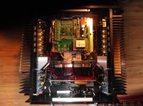
Whether I put a 500va or 1kva in the case (below) , you can still have a small
professional amp with a lot of extra horsepower ... 🙂
IT does not have to be a big "clunky" (DIY ) looking piece.
PS - that's the EBAY 170$ chinese case , BTW.
OS
Attachments
So you use simulation to find the bias current of the power transistors?Is it a larger class A region , or just being in the "sweet spot" of optimal class AB -that makes it "sound better" ?
Do you mean the emitter resistor in between Q26 and Q27 in my schematic? Even if I don't use a 1N4007 diode to take up 0.7V I use 27ohm resistor to draw 50mA of tail current from Q26 and Q27. If my guess is right that you use 100ohm between the two emitters? That would be 14mA or so of tail current only!!!What does make a big difference is having a optimal value for the "suckout cap" at
the main driver Re. .68u - 1u with 100-150 Re at the drivers is standard fare for
the 2K pf Cob of 3-5 output devices.
Do you mean you put a 1uF cap across the 100ohm resistor between the two emitters? Like I put a 10uF//01.uF between the two emitters of Q26 and Q27?
I have not even start to think about simulation, I figure this only affect the value of the components. The most important thing for me is to get the pcb right so I am covered for all possibilities. Do yo use LTspice? that's what I have. Just need to find the model of all the transistors.
Thanks
Last edited:
Nice looking case, and an interesting perspective on crossover distortion. 🙂
I personally don't think a 625VA tranny would be overkill, if you were running 50V rails.
Where do you guys get your KSA3503 etc.
I personally don't think a 625VA tranny would be overkill, if you were running 50V rails.
Where do you guys get your KSA3503 etc.
That's a nice looking guts. Where is your toroidal transformer? Is that an inductor on the pcb in the middle that looks like a small transformer?Whether I put a 500va or 1kva in the case (below) , you can still have a small
professional amp with a lot of extra horsepower ... 🙂
IT does not have to be a big "clunky" (DIY ) looking piece.
PS - that's the EBAY 170$ chinese case , BTW.
OS
What is your power filter? Is it CLC? What value are you using?
- Status
- Not open for further replies.
- Home
- Amplifiers
- Solid State
- Please comment on my OPS design