Hello,
I hope I'm posting this on the correct section!
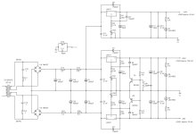
This is my first attempt in designing a linear power supply and after a few days of intensive reading (my brain has melted) I've settled to this design.
I have too many questions to ask but it would be great if you could critique my design for starters...")
Thank you all in advance!
I hope I'm posting this on the correct section!
This is my first attempt in designing a linear power supply and after a few days of intensive reading (my brain has melted) I've settled to this design.
I have too many questions to ask but it would be great if you could critique my design for starters...
Thank you all in advance!
Attachments
You can click "report" and ask moderators to change the title.
You have about 10 ohms series resistance (seems high) in the positive rail with a 340 mA load. That will drop the available unregulated voltage by 3.4 V. The regulator needs another 3 V of headroom.
So make sure you always have enough voltage, considering rectifier voltage drop, ripple and 10 % mains voltage variation!
Edit: not sure about the 100 uF output cap, might be a bit high...
Last edited:
Hi stv and thanks for the reply,
The reason I chose a 2x28V 50VAC transformer is that even in worst case scenario of 10% mains drop, the pre-regulated voltage should be around 32V. So, that's approx Vi-Vo=4V which should be sufficient(?). At leats, these are the results I got from the PSUD2 if I used the correct transformer's properties.
Now, the thing is that in a 10% mains increase the Vi would be around 40V so the regulators should drop around Vi-Vo=12V for the +/-28V regs and Vi-Vo=16V for the +24V rail. That's a lot...
Regarding the resistors, to be honest, I'm not sure what the resistor values should be. That's mostly because I don't know what ripple I should be aiming for. Perhaps I could increase the caps and drop the R but I'm not sure if it's a good idea.
P.S. I appreciate your comment because ideally I would like to go from left to right on the design/ corrections
Last edited:
My calculation:
Nominal output = 28 Vac
Mains variation -10% = 25.2 Vac
Rectifier drop -1.2 V = 24 V
Peak voltage (ideally smoothed voltage, drops with every discharge cycle) = 33.6 Vdc
Series resistor 10 Ohm - 3.4 V = 30.2 V
That does not leave enough regulation for the 317 (min 3 V), not even considering ripple.
I would reduce the series resistors for the 28 V positive rail. Generally the CRCRC network will not change much, considering the active regulation of the 317 (but if course that's debatable).
If you are looking for minimum noise you could also look at elvee's D-noizator circuit:
https://www.diyaudio.com/community/...-retrofit-upgrade-any-317-based-v-reg.331491/
That is quite common for linear regulators ... but yes, you need heatsinks on the regulator!That's a lot...
Please don't quote me on this but my understanding is that a 28VAC secondary will in fact output more than 28V depending on the transformer's regulation. Considering a regulation between 10%-14% for a 50VA transformer, the secondary should output anything between 30.8Vac to 31.9Vac.
So, that'll be:
Min Sec output for a nominal 28Vac = 30.8Vac
Mains variation -10% = 27.7 Vac
Rectifier drop - (say) 2V = 25.7 V
Post FBR voltage - 25.7 x 1.414 = 36.3V
Series resistor 10 Ohm - 3.4 V = 32.9V pre-regulated
I might well be wrong though...
Thanks for the D-noizator suggestion. I'm aware of it but I'd like to keep it simple for now. One step at a time. Maybe on a future design.
With a 28 Volt AC transformer you will see about 40V DC at idle. This voltage drops a little under load, but in most cases less than one might expect.
A 24V AC should do and have more current.
There are very capable, symetric regulators out there, you may buy a kit and replace Chinese parts by better ones if you like. Look at Aliexpress.
https://www.aliexpress.com/item/4000248244657.html
A 24V AC should do and have more current.
There are very capable, symetric regulators out there, you may buy a kit and replace Chinese parts by better ones if you like. Look at Aliexpress.
https://www.aliexpress.com/item/4000248244657.html
The eventually not enough regulation voltage and peace of mind "issue"What issue?
With a 28 Volt AC transformer you will see about 40V DC at idle. This voltage drops a little under load, but in most cases less than one might expect.
A 24V AC should do and have more current.
There are very capable, symetric regulators out there, you may buy a kit and replace Chinese parts by better ones if you like. Look at Aliexpress.
https://www.aliexpress.com/item/4000248244657.html
Hi Turbowatch2, thanks for chiming in.
Can you elaborate a bit please? You mean I will see 40V DC at Vi of the regs even with the 3.3R and 6.8R?
Also, a 24VAC will run sort with a 10% mains drop, no? The pre-regulated voltage will be well below the 28V+3V needed for regulation.
Finally, why would I need more that 900mA for this specific requirements/ design?
Thanks for the link but I would like to treat this as a case study so I can hopefully learn something along the way.
By the way, you could reduce rectifier voltage drop by using only one rectifier and connecting ground to one central transformer tap (connect the secondary windings.peace of mind
It would help if you told us what kind of load you have to drive.
With 24V AC and 50VA transformer you get more A. Which makes the unregulated voltage more stable. The regulators have to burn less power.
So in a real world scenario you should be better of with the lower voltage transformer with 1A current, at a 340mA load which is still a 3 times overdimensioned transformer.
If you are new to electronics and audio, you may think you have to overdimension anything. This may be right if you use Chinese components.
Anyway, in serious western electronics, a 500mA transformer can drive a 500mA load all day long.
A "normal" transformer will drop very little in voltage when you use only a third of it's load. So your regulator still has to deal with an input voltage near to idle level.
Things may get different when you use an 25VA transformer. In this case I would rather pick a 28V version.
Make your own experiments with transformer load and you will see I'm right.
A very large capacitor after the recifier evens out the voltage even more, This is where the type of load get's interesting. Something audio will have a very dynamic current demand. So you can get away with a smaller transformer using large caps. 1.500uF can drive a small amp quite well...
Without a list of design requirements it is difficult to judge the suitability of your circuit.Hello,
I hope I'm posting this on the correct section!
This is my first attempt in designing a linear power supply and after a few days of intensive reading (my brain has melted) I've settled to this design.
I have too many questions to ask but it would be great if you could critique my design for starters...
Thank you all in advance!
show me any "serious western electronic" component that's not made in chinaserious western electronics
The ciruit in question would be a class A mic preamp so my understanding is that this would be the total (constant)current draw and therefore no fluctuations will occur(?). The +24Vdc is there for all the leds/ relays and other dirty stuff.
I'm really straggling to figure out how a 24V secondary can provide 28Vdc regulated with the 3.3R and 6.8R, let alone if the mains have a 10% drop. But even without the resistors, the pre-regulated voltage would sit at around 32V and that's with ideal mains. I would think that a minimum of 2 x 25Vac @ 50VAC is required. A minimum.
Most likely I'm missing something but quite frankly this puzzles me.
What sort of requirements other than the required Vdc and the current draw?Without a list of design requirements it is difficult to judge the suitability of your circuit.
I did think of Chinese components sourced on eBay and Aliexpress without "real" specification.show me any "serious western electronic" component that's not made in china
If you buy from "serious" sources you can be quite sure the component meets the suplied specifications. Of course they are from China in most cases. Something that may need to change, for some obvious reasons.
With 25V x2 @ 50VA I can power a nice sounding amp that will drive a grown up speaker. In Stereo.
There may be something not perfectly right with your preamp. Why do you need so much power?
In most cases a microfone preamp doesn't need to supply that much current, may it be A or A/B or valve. Just voltage. A few Volt.
There may be something not perfectly right with your preamp. Why do you need so much power?
In most cases a microfone preamp doesn't need to supply that much current, may it be A or A/B or valve. Just voltage. A few Volt.
- Home
- Amplifiers
- Power Supplies
- Please comment on my design!