Say we have a pair of beam tetrodes that need a load impedance of 8K plate to plate. Then we decide to put the centre tapped output tranny in the cathode circuit instead. Would the right load still be 8K? Obviously the circuit would have a lower output impedance, but it can still only pull the same peak current as before, so what's the go with selecting the right load?
"Small signal" impedance will change, putting load on cathodes so they become unity gain followers will change that because you are adding a lot of "built in" NFB.
Among other effects (lowering output impedance) this brings stage gain down so much that now you need hundreds of volts driving signal.
But that does not change "large signal" parameters, possible current and voltage swing will be basically same as before so for maximum power you will get it on same load impedance as before.
I think the answer to your question lies in how it was initially decided that 8k was the correct load for the anode/plate connected setup. Basically selecting the impedance matching becomes a compromise of power output and what kind of distortion profile you are aiming for.
Lower impedance load will give higher linearity at lower power as the anode voltage swing is smaller, but you sacrifice maximum output power and clipping will be harder/harsher.
As above, if the voltage and current swing at the load have not changed and neither have your goals for output power and distortion then the load impedance needn't change either.
Last edited:
No, 8k is between anodes, one tube sees 4k in class A and 2k when it passes into class B.Say we have a pair of beam tetrodes that need a load impedance of 8K plate to plate. Then we decide to put the centre tapped output tranny in the cathode circuit instead. Would the right load still be 8K? Obviously the circuit would have a lower output impedance, but it can still only pull the same peak current as before, so what's the go with selecting the right load?
In a circlotron the tube uses the whole winding for itself. That is 2k cathode to cathode and from cathode to centertap ½k. In class A the tubes shares the load, each only half load to pull like it is 4k.
Mona
You didn't say circlotron in your post, but is this for a circlotron? That one is a special case.
Normally, though, you choose the same total turns ratio whether the load is all in the anode, all in the cathode, or some split between the two.
Putting some of the load in the cathode circuit results in some series voltage feedback and lower output impedance.
Normally, though, you choose the same total turns ratio whether the load is all in the anode, all in the cathode, or some split between the two.
Putting some of the load in the cathode circuit results in some series voltage feedback and lower output impedance.
The name of the TS 😕You didn't say circlotron in your post, but is this for a circlotron?
Mona
The name of the TS 😕
Mona
Right, that's why I'd like clarification. Just because someone is named circlotron doesn't mean they always have to be talking about them. But it seems likely in this instance.
I always thought making a top-quality circlotron would be fun (not OTL). It is a fascinatingly clever circuit, but it demands a lot of effort to build all of the floating supplies.
If you build a push pull cathode follower circuit, and you are going to use an 8k push pull transformer, you need to check one thing:
The maximum Filament to Cathode DC + peak AC voltage ratings of the output tubes.
Quite often these maximum ratings are different for Filament + to Cathode -, versus the Filament - to Cathode + rating.
Of course if you are going to use DHT tubes, the Filament and Cathode are the same device (bet you did not think about that).
In my Unity-Coupled amp I used an individual small Hammond heater transformer for each power tube and tied the center tap to the cathode. It's one possible solution.
What?
Nobody volunteered to use DHTs in such an amplifier?
Where is your sense of adventure?
And yes, you also need 2 independent filament supplies for DHTs too.
For example,
A 2A3 rp is 800 Ohms.
A 2A3 filament follower impedance is 182 Ohms.
Consider the lower impedance transformer primary when using a 2A3 filament follower.
Last edited:
Well, okay, yes. It is for a circlotron!Right, that's why I'd like clarification. Just because someone is named circlotron doesn't mean they always have to be talking about them. But it seems likely in this instance.
I always thought making a top-quality circlotron would be fun (not OTL). It is a fascinatingly clever circuit, but it demands a lot of effort to build all of the floating supplies.
For such a circuit you have to put the right load in the plate circuit but I wasn’t sure if it would be happy with the same load in the cathode circuit. Just toying with a few ideas at the moment. I have a pair of 120+120V to 28V 200VA toroids, and with just one in the plate circuit alone it it would reflect about 588 ohms plate to plate with an 8 ohm load. However, with the second toroid in the cathode circuit (and both secondaries parallel) we now get twice the turns ratio and 4 times the impedance ratio, 2351 ohms. Still very low but a big step forward. Add big cross coupling capacitors from each cathode to the opposite anode to lock the corners together so that each valve would drive the full winding of both transformers. Higher efficiency and no chance of a non driven end of a transformer ringing in the breeze. And what’s more, if I connect each screen to the B+ supply it is the same as connecting to a 50% ultra linear tapping on a transformer! Remember, at full drive the cathodes will rise to 50% of B+ voltage. The thing is still in the thinking-about stage... One thing is for sure, I’ll need lots of grid drive voltage!
PS with two transformers like this you don’t need floating supplies. Except for the valve heaters maybe, to prevent excess heater to cathode voltage.
Last edited:
Well, okay, yes. It is for a circlotron!
It's been a while since I have thought about circlotrons but if I remember correctly, you want to get a transformer that is 1/4 the impedance of a typical plate load configuration because of the way the windings are driven and shared between the two tubes. If you have a 1.25k transformer, the output tubes will traverse the same load line that a typical plate-loaded configuration with a 5k plate-to-plate transformer. This makes it a bit hard to find suitable iron as most 1.25k transformers will be huge, made for parallel output tubes. You are solving that another way.
I'd love to see your configuration that avoids floating supplies.
I built a Unity-Coupled amplifier without a bootstrapped driver, which taught me a thing or two about developing high swings at low distortion. You may wish to review my experiments with CCS-loaded pentodes as high-swing drivers: Idea for driver for CF output stage
What?
Nobody volunteered to use DHTs in such an amplifier?
Where is your sense of adventure?
Yes, I have thought about it. Enough to plan it all out.
However, I think I figured out easier ways to get similar performance with a simpler circuit. And now I'm building my first DHT amp.
Nothing particularly new about it, fairly similar to what McIntosh used way back. Imagine one transformer primary from plate to plate with the CT connected to B+. The second transformer primary goes from cathode to cathode with the CT connected to ground. Two capacitors, say 50uF, each going from one cathode to the opposite anode. That's it really. The McIntosh version had it all wound on one transformer, and back in the day you could probably get transformers like that at any corner drugstore but now they're just a little hard to come by so I've used two separate transformers. Also, some Mcintosh schematics don't show any cross coupling capacitors, so some models may have used them and some not.I'd love to see your configuration that avoids floating supplies.
Some years ago I built a similar setup using mosfets, with a single hand wound transformer. Worked REALLY well, and the interesting thing about it was seeing the load was connected to the two mosfet source, the circuit didn't depend on the quality of the transformer at all. It was there simply to supply DC power to the nodes that were bouncing up and down with the signal. The cross coupling capacitors transferred the audio and made sure each end of the transformer behaved itself.
Here it is -> Tetrahedron output stage topology.
Last edited:
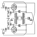
This is what I am thinking about. Nothing new under the sun of course.
http://www.dissident-audio.com/Yves/1960crowhurst.pdf
http://www.dissident-audio.com/Yves/1960crowhurst.pdf
By making the draw a little different makes it more clear.
If you apply the supplys on the two inter transformer capacitors it's a circlotron with two coupled irons.
By puting the supply on the mid to ground capacitor it's a tetrahedron.
The transformers are coupled so the inductance remains more or less the same but the interwinding capacitance doubles.On the other hand, the capacitances from the double supply are gone.And no UL what so ever, the g2 is coupled to the cathode.
Mona
Attachments
Yep, that circuit is pretty much it alright. Running the grid resistor to the cap that goes to the cathode is a very good idea! Haven't seen that before. Thanks for showing that.
Not in that circuit, but you can have 50% UL if you run the screens to B+.And no UL what so ever, the g2 is coupled to the cathode.
Mona
Yes, but that's an awful lot.Normally between 20...40%.With 50% the screen goes very low and the bottom voltage of the anode goes up resulting in less power.Not in that circuit, but you can have 50% UL if you run the screens to B+.
Mona
Circlotron,
The more complex a circuit is, the more likely it is that there is a disadvantage.
Positive feedback to the drivers in order to increase peak driver swing (very large driver voltage swing required),
very expensive and complex output transformers, . . .
Tradeoffs, tradeoffs, tradeoffs.
And . . . Mona, thanks for your many enlightening posts.
Last edited:
Ah yes, I'm familiar with the twin-coupled configuration. It's pretty cool and allows you to use some fairly standard-type transformers. The obvious downside is you need two output transformers per channel, but not a deal breaker in my opinion.
Here's an old write-up of my design: Tube Amps with a Twist: A Unity Coupled KT88 Amp with Plitron Transformers
I've changed the circuitry quite a bit since then so I really should do an update.
The thing I want to point out to you is that it is quite easy to drop the screen voltage and be kinder to the screen than the McIntosh amps were.
- Home
- Amplifiers
- Tubes / Valves
- Plate to plate vs cathode to cathode - load impedance