This amp came in and someone else has been messing with it.
Power supply seems to work ok since the rail voltage is 73V.
I would like to verify some mods/changes to the circuit.
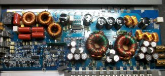
The power supply fets are replaced with RFP70N06.
Will those work reliably (gate resistor is 47R).
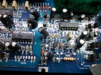
There is a 56K resistor connected to pin 2 of 494...
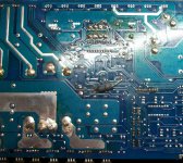
There is also a 270R/2W resistor on the underside of the board...
In the class D section the hip4080 is missing and i am going to replace all output fets with IRF3710Z.
I do not know if it is of any importance but here are the readings i get at the ic socket without the 4080 on and without any output fets on.
1. 11.6
2. 11.9
3. 0
4. 0
5. 0
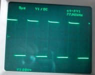
6. a nice triangle of 78KHz
7. a nice 100Hz sine (thats what i feed the amp with)
8. 0
9. 0
10. 11.6
11. 0
12. 6
13. 0
14. 0
15. 11.9
16. 11.9
17. 0
18. 0
19. 6
20.0
Power supply seems to work ok since the rail voltage is 73V.
I would like to verify some mods/changes to the circuit.
The power supply fets are replaced with RFP70N06.
Will those work reliably (gate resistor is 47R).
There is a 56K resistor connected to pin 2 of 494...
There is also a 270R/2W resistor on the underside of the board...
In the class D section the hip4080 is missing and i am going to replace all output fets with IRF3710Z.
I do not know if it is of any importance but here are the readings i get at the ic socket without the 4080 on and without any output fets on.
1. 11.6
2. 11.9
3. 0
4. 0
5. 0
6. a nice triangle of 78KHz
7. a nice 100Hz sine (thats what i feed the amp with)
8. 0
9. 0
10. 11.6
11. 0
12. 6
13. 0
14. 0
15. 11.9
16. 11.9
17. 0
18. 0
19. 6
20.0
Attachments
I don't know if the resistors are OEM mods.
I don't see anything out of the ordinary on the voltages that you posted.
The 47 ohm resistors should be OK with those power supply FETs.
Don't attempt to power this amp up without the 4080 in the socket (after installing the outputs) unless you confirm that the output transistors have pull-down resistors.
problems
Lots of problems with this amp.
To start with, someone had inserted a 56K resistor to pin 2 of the 494 in order
to lower the rail voltage to about 63V.
This eventually made the auxiliary power supply to produce less voltage....
So, with the 4080 removed i had only 9.4V on pins 15 and 16.
Checked the 7812 that feeds these pins, and i had less that 10V on pin 1.
After removing the 56K resistor, the rail voltage went up to 73V and i finally
got 12V on pins 15 and 16 of 4080.
Replaced output fets with irf3710z and amp seems to work ok.
At very low volume, my test speaker sounds ok.
Then i clamped everything back to the heatsink and put a 4 ohm load to
bench test the amp.
There is a sign of instability at high power-just over 80A of current draw.
My ammeter goes up and down around 80 to 95A, while at the same time
the 100Hz sine wave at the output seems to have some "cracks" like there is
also another (square) wave curve...
Ok, now upon loading the amp (at high power) the ammeter starts to "tremble"
and finally shuts down.
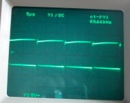
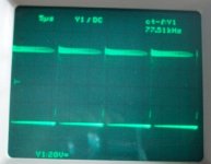
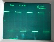
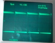
There are 4 sets of pics, the first of each set is the gate drive at idle and the
second of each set is the same gate at 800W rms (around 40VAC)
pic1 is AHO at idle
pic2 is AHO at 800w
pic3 is ALO at idle
pic4 is ALO at 800w
pic5 is BLO at idle
pic6 is BLO at 800w
pic7 is BHO at idle
pic8 is BHO at 800w
The load is always 2 ohm.
I suspect the rail caps....
and finally shuts down.
There are 4 sets of pics, the first of each set is the gate drive at idle and the
second of each set is the same gate at 800W rms (around 40VAC)
pic1 is AHO at idle
pic2 is AHO at 800w
pic3 is ALO at idle
pic4 is ALO at 800w
pic5 is BLO at idle
pic6 is BLO at 800w
pic7 is BHO at idle
pic8 is BHO at 800w
The load is always 2 ohm.
I suspect the rail caps....
Attachments
-
 BHO at idle.JPG57.2 KB · Views: 43
 -
 BLO at 800W 2 ohm.JPG55.9 KB · Views: 54
 -
 BLO at idle.JPG48.4 KB · Views: 55
 -
 ALO at 800W2 ohm.JPG286.2 KB · Views: 56
 -
 ALO at idle.JPG52 KB · Views: 52
 -
 AHO at 800W 2 Ohm.JPG50 KB · Views: 105
 -
 AHO at idle.JPG60.3 KB · Views: 104
 -
 BHO at 800W 2 ohm.JPG51.4 KB · Views: 55
Last edited:
I don't see anything obviously wrong. Did you replace all of the outputs or only half?
If the rail caps were bad, I'd expect to see a lot more ripple on the tops of the waveforms.
Have you tried it with a battery?
If the rail caps were bad, I'd expect to see a lot more ripple on the tops of the waveforms.
Have you tried it with a battery?
- Status
- Not open for further replies.