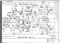
This is turning out to be a long running project. I have replaced caps and faulty transistors and the odd diode on the two power amp assembly boards and power supply boards. The amp now turns on, nothing burns or blows but the output to the speakers is left channel only whilst the right channel is crackly and squeeky.When I turn the power up the protection circuit cuts out but returns when reduced again. I have checked the voltages to the output transmitters 2sc1116a and 2sa747a and they both are all getting the correct voltage at the base. For Q1 and Q2 I am not getting any reading at 14 and 15. For Q5 and Q6 I get readings at 17 and 18 which is my left channel signal. I get no reading on the second board at 14 & 15 & 17 & 18. although they are receiving the correct power through 10 & 13 on both boards. When I have removed the transistor Q1 and tested it red to base both pins do not read yet black to base reads on one pin which would I think indicate PNP but the schematic shows NPN. I have the leads into my multi meter correctly which I suspected when all checks seem to be in reverse. I am probably doing something wrong and would appreciate guidance as I am fairly new to this. I have tested all the output transistors Q1 to Q8 and found one shorted. What is fooling me is that when I measure across the pins c & e I get readings and thought that they should be zero. Have attached schematic.
Attachments
Am I correct in assuming the channel with zero or near zero is working correctly and the other channel is at 185mv at idle has problems?
If it were me I would go back thru and match up a pair of diff transistors and replace the feedback cap and re-check. It has a problem in the front end in my opinion. I owned one of these receivers once and they seem to be problematic in my opinion.
If it were me I would go back thru and match up a pair of diff transistors and replace the feedback cap and re-check. It has a problem in the front end in my opinion. I owned one of these receivers once and they seem to be problematic in my opinion.
the odd diode on the two power amp assembly boards and power supply boards.
Did you mean the STV-3H diode? Black box thing that screws to the heatsink?
If so, this cannot be replaced without a lot of effort. It is super rare (not available anywhere) and a normal diode will not cut it. If you replaced it with a standard diode, things are not going to work as intended. This is a triple-diode with rather unusual specifications. Three 1N4148 diodes in series is a close match, but not quite right.You will also need to get proper thermal coupling to the heatsink, which can prove tricky.
Channel with zero or near zero is working. It has two power amp boards and I think only one is working correctly being the one with the Q3 and Q4 output transistors. Looking at my schematic which are the two diff transistors and feedback cap. Sorry for my lack of experience.
I have not replaced the STV-3H diode.
I have not replaced the STV-3H diode.
I would replace the Q1 and Q2 2SA726's with Fairchild KSA992FTA which are available for about 6.40 a hundred. You will need to closely match a pair. You will need a meter to match the HFE or construct a circuit to match some. Do the other channel as well. Replace C8 330/6
You don't really need to match KSA992 if you buy them today. They all have practically the same hFE.
Previously I checked the transistors 2SA726 on the board and they read ok and changed all caps. Will they effect the readings from the transistors Q1 & Q2 Sc1116a which are attached to the main large heatsinks on the right end of the schematic. Sorry if this seems a very stupid question but as they are receiving voltage at the base I would expect to see a reading on their output.Terminals 16 and 17 have a reading for Q5.
Previously I checked the transistors 2SA726 on the board and they read ok and changed all caps. Will they effect the readings from the transistors Q1 & Q2 Sc1116a which are attached to the main large heatsinks on the right end of the schematic. Sorry if this seems a very stupid question but as they are receiving voltage at the base I would expect to see a reading on their output.Terminals 16 and 17 have a reading for Q5.
With respect to the diff input transistors.... they may check ok but when your getting excessive and high DC offset they need to be changed.
Just because a transistor checks ok doesn't mean it is ok or behaves ok. You have a handfull of cheap transistors just replace them with new ones. How did you check these transistors? Do you have an honest to goodness transistor testor that checks leakage or a $5 rat shack transistor tester?
You don't really need to match KSA992 if you buy them today. They all have practically the same hFE.
Thanks I will keep that in mind. I'm used to having to purchase bulk and match them.
I checked them with my multimeter removed from the board. Many thanks for your help and I will change these transistors. Can you tell me the equivalent transistors for both channels as I will change them all.
I have checked them with my multimeter. Thanks for your assistance and I will change the transistors. Could you tell me the equivalent for the other channel as I will change those as well to be on the safe side. Thankyou again.
- Status
- Not open for further replies.
- Home
- Amplifiers
- Solid State
- Pioneer sx 1010 output transistors