Hey everyone.
I'm new here and trying to get into electronics repair as a hobby.
I recently came into a Pioneer SA-1050 in fantastic condition, but the channels didn't work. Did the usual pot/switch clean and got it running like a champ.
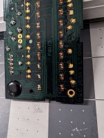
However, some of the VU meter LEDs had burned out. I had never done SMD repair before, but thought what the heck the meter is right on the front, I'll give it a shot.
I got a cheap hot air rework station, the right replacement LEDs (https://www.mouser.com/ProductDetail/Kingbright/APHD1608LCGCK?qs=AQlKX63v8RvqPbV1LDSVuw==&countryCode=US¤cyCode=USD).
I confirmed polarity on the original ones that worked, began floating the old ones off, replaced three, and went to test. When I connected the VU meter to the amp and powered it on, the relay did not click and I saw smoke begin to come from a particular spot! I immediately shut the unit off, and removed the VU board.
I powered the unit back on without the VU board in, the relay clicked, and began playing music as if nothing was wrong.
I went ahead and removed the 3 LEDs I had replaced, checked that I hadn't shorted any traces with solder, and reinstalled the VU meter without the LEDs into the unit. It played fine, with a now-unlit VU meter.
I rechecked polarity, rechecked traces, reinstalled the three LEDs, and re-attempted. Same thing, a little more smoke. Immediately shut off again, and removed the VU meter. Now the left channel was heavily distorted, I thought I lost the channel. I let it cool down for about 10 minutes and retested without the VU meter. Left channel was back!
I now have a "dead" VU meter and am entirely unwilling to retest my skills for fear of killing the amp for good. It's an absolute testament to the durability of this older hardware. The amp sounds great to me, and I dearly don't want to risk losing it; I fear I've already removed some of its remaining life, and the schematics available for the unit I could find are pretty rough to read. (So I REALLY don't want to lose this unit).
I apologize for the low-light conditions in the pictures. I have lighting issues in my shop.
Would anyone be kind enough to allow me to mail them the VU meter to take a closer look and tell me where I went wrong?
Thank you in advance!!
Jordan
I'm new here and trying to get into electronics repair as a hobby.
I recently came into a Pioneer SA-1050 in fantastic condition, but the channels didn't work. Did the usual pot/switch clean and got it running like a champ.
However, some of the VU meter LEDs had burned out. I had never done SMD repair before, but thought what the heck the meter is right on the front, I'll give it a shot.
I got a cheap hot air rework station, the right replacement LEDs (https://www.mouser.com/ProductDetail/Kingbright/APHD1608LCGCK?qs=AQlKX63v8RvqPbV1LDSVuw==&countryCode=US¤cyCode=USD).
I confirmed polarity on the original ones that worked, began floating the old ones off, replaced three, and went to test. When I connected the VU meter to the amp and powered it on, the relay did not click and I saw smoke begin to come from a particular spot! I immediately shut the unit off, and removed the VU board.
I powered the unit back on without the VU board in, the relay clicked, and began playing music as if nothing was wrong.
I went ahead and removed the 3 LEDs I had replaced, checked that I hadn't shorted any traces with solder, and reinstalled the VU meter without the LEDs into the unit. It played fine, with a now-unlit VU meter.
I rechecked polarity, rechecked traces, reinstalled the three LEDs, and re-attempted. Same thing, a little more smoke. Immediately shut off again, and removed the VU meter. Now the left channel was heavily distorted, I thought I lost the channel. I let it cool down for about 10 minutes and retested without the VU meter. Left channel was back!
I now have a "dead" VU meter and am entirely unwilling to retest my skills for fear of killing the amp for good. It's an absolute testament to the durability of this older hardware. The amp sounds great to me, and I dearly don't want to risk losing it; I fear I've already removed some of its remaining life, and the schematics available for the unit I could find are pretty rough to read. (So I REALLY don't want to lose this unit).
I apologize for the low-light conditions in the pictures. I have lighting issues in my shop.
Would anyone be kind enough to allow me to mail them the VU meter to take a closer look and tell me where I went wrong?
Thank you in advance!!
Jordan
Attachments
Replacing the LEDs and shorting themout won't cause what you describe.
Use your DVM to determine that the LEDs weren't actually faulty and it was the drivers that failed.
Check your connections to the main board.
You will need the service manual but unlikely to find one as it was made in January 1984!
Use your DVM to determine that the LEDs weren't actually faulty and it was the drivers that failed.
Check your connections to the main board.
You will need the service manual but unlikely to find one as it was made in January 1984!
HifiEngine has the SM for the SA-1040.
I would disconnect the VU-meter board and apply external voltage to it but limit the current (12V/80mA). If it works, and from what you describe it does without the new LED's, replace 1 LED and test again. Then another LED, and so on. You will probably need to create the Vref with the two 100k resistors as shown in the manual. If the fully populated board works, I would think the problem lies somewhere else.
Hugo
Replacing the LEDs and shorting themout won't cause what you describe.
Use your DVM to determine that the LEDs weren't actually faulty and it was the drivers that failed.
Check your connections to the main board.
You will need the service manual but unlikely to find one as it was made in January 1984!
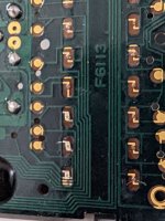
When you say "driver" do you mean the black-potted IC that appears to have traces leading to all the LEDs? Could a failure here cause excessive current draw if one shorted? Perhaps I hit one with too much heat nearby from the rework gun?
AKA Chip "IR2431".
Last edited:
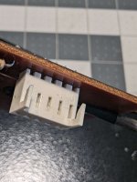
It might be worth just measuring between the supply and ground (pin 3 and pin 4 on the connector) with your meter on ohms just to make sure you haven't accidently applied a short anywhere with a solder blob or whisker.
Assuming the "arrow" on the pinout connector = 1 (rightmost pin on connecter in picture), I tested the two pins starting second from the left, and got 15mohms. There are resistors on the back of the board that share a trace with these pins. I will confirm color code ASAP.
Attachments
I doubt it. I would suspect there is no drive to the LEDs that had failed but if there is, placing your DVM across each LED on diode test, should light each individual LED up.When you say "driver" do you mean the black-potted IC that appears to have traces leading to all the LEDs? Could a failure here cause excessive current draw if one shorted? Perhaps I hit one with too much heat nearby from the rework gun?
AKA Chip "IR2431".
The driver IC is a transistor ladder, nothing sinister, and they do fail.
Have fun fixing this iconic amplifier, I trust you will restore it to its formal glory.
When putting 12v to Pin 1 and 4 and Pin 2 and 4, I get no response in LEDs. I can light up individually the three I installed, but it is a struggle to get the OE ones to illuminate.
So, Jon, to confirm, I CAN get LEDs to light up individually at 2-3v, but cannot get a response when injecting 12v through the circuit.
Does that information help the diganosis? Thanks for armchairing!
Edit: The two identical resistors in the circuit on the back of the board are 82kohms.
So, Jon, to confirm, I CAN get LEDs to light up individually at 2-3v, but cannot get a response when injecting 12v through the circuit.
Does that information help the diganosis? Thanks for armchairing!
Edit: The two identical resistors in the circuit on the back of the board are 82kohms.
Last edited:
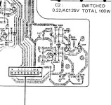
This seems to be the pinout for the IR2431 chips so you can confirm the plug/socket connectors from here. Ground is pin 11 and supply is pin 22.
When you said something smoked it could have been this resistor in the supply to the VU board.
I'm not sure how much you know about LED's 🙂 but its worth mentioning that they are very low current devices and you can not apply a normal voltage directly to them as that will instantly burn them out. The chip does the limiting here. For testing them out of circuit you need a voltage such as 9 or 12 volts PLUS a series resistor to limit current. Something like a 1.5k or higher would be fine.
I assume you took the board out of circuit.
12V should be applyed on pins 3 & 4, pin 4-, pin 3+. Pin 1 & 2 are audio signal inputs. So, with 12V but without audio the LEDs will never light up.
You will need the two 100k resistors as shown in post #3 to make the board work as intended.
Also, look again at the schematic in post#3. The pin numbers are not in a logical order. Find the GND pin first and measure from that reference.
It is the one that connects to the two 82k resistors.
Hugo
Exactly, the schematic specifies 80mA.PLUS a series resistor to limit current
Hugo
That's right where I saw the smoke!! That area! One of the color bands looks like it's tried to lift off. Just spec'd it out: 33.30ohms. Looks good! Visual inspection of other component damage negative. I'll if I can spec Q405 and Q406 as well.This seems to be the pinout for the IR2431 chips so you can confirm the plug/socket connectors from here. Ground is pin 11 and supply is pin 22.
When you said something smoked it could have been this resistor in the supply to the VU board.
I'm not sure how much you know about LED's 🙂 but its worth mentioning that they are very low current devices and you can not apply a normal voltage directly to them as that will instantly burn them out. The chip does the limiting here. For testing them out of circuit you need a voltage such as 9 or 12 volts PLUS a series resistor to limit current. Something like a 1.5k or higher would be fine.
View attachment 1192318
View attachment 1192319
Attachments
It's bedtime here, I'll pick this up with you all tomorrow. Thank you SO MUCH for the continued help!
The transistors are most likely just fine. At this stage as long as the 12 volt supply is OK then all is well.
Spec'd 12-13v at Q405 and A406. Suspect possible that R406 let out a little magic smoke. I think the LED driver board is kaput. It won't light up at all now; only individual LEDs and no response through the connector when given 12v. I suspect I created a short on the board with some errant solder, R406 shouldered the load, and the board fried.
Possibility?
As expected with the circuit working in the chassis-side, the pinout sticking out of the chassis shows fluctuating mV in accordance with VU signals.
Possibility?
As expected with the circuit working in the chassis-side, the pinout sticking out of the chassis shows fluctuating mV in accordance with VU signals.
Anything's possible 🙂
Its a bit unlikely both channels of the meter would be duff though. The diagrams for the meter in the manual for some reason don't seem to be detailed. No IC pin numbers, no resistor markings etc. That area is shown more as a block diagram which makes things a bit harder.
If I was fixing that I would look at removing the driver chip for one side and concentrate on getting one channel working. Power it up from a separate supply (even a 9v battery might be usable). First check would be power consumtion. With no LED's lit it should only be a few milliamps. Any more and the chip is suspect... in which case swap for the one removed and retest.
That would be my starting point.
Hi Mooly, I fear the IC's might have been toasted by this...When putting 12v to Pin 1 and 4 and Pin 2 and 4
Hugo
Rookie Mistake! Still learning. Can you explain my mistake?Hi Mooly, I fear the IC's might have been toasted by this...
Hugo
Weirdly, and I'll describe this as best as I can. But when I leave the amp to sit, usually overnight, I will power it up and get significant distortion in the left channel. This happens across all inputs. However, if I unplug and reverse the RCA cables and then reverse them back to proper input, the distortion. immediately clears up and the amp plays great on both channels! I can get it to consistently do this.
Can anyone shed some light on this?
Last edited:
Hi Mooly, I fear the IC's might have been toasted by this...
Hugo
I see what I did. I did exactly the opposite that you described. I am very good at doing this.
I likely put voltage to both the audio-in signals and like you said toasted the ICs with 12v.
- Home
- Amplifiers
- Solid State
- Pioneer SA 1050/1040 VU Meter