I've had this thing since the 90;s and used it mostly as a cd player. A few months ago I was sitting here reading the paper and I heard a loud pop and smelled something electrical. It took me a while to figure out where it came from but I finally noticed that the light was flickering on my power strip/surge protector for the stereo.
When I tried everything the DVD player wouldn't work, completely dead. It was plugged in to the receiver's switched power outlet
The receiver works fine.
I pulled it from the rack and pulled the cover and right away saw the fuse was popped, so i tried a new fuse.
When I did I got an even bigger pop and the first part in line beyond the fuse, Z101, which looks like some sort of capacitor or thermistor?
I don't recognize the symbol but I'm used to Z being used on Zener diodes but this thing has a capacitor type symbol with a slash through it.
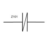
The diagram doesn't seem to say what Z101 is.
I've been trying to figure out what went on here because this is all before the power switch and the power should have been absent from the cord with the receiver off. I put a different CD player in its place for now and the receiver and outlet work fine?
There's a 241 and a 96 on the part that popped, to me it looks like a ceramic capacitor but its graphite inside, the dust it blew off was like pencil lead all over the area.
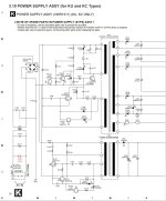
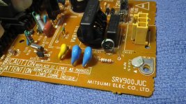
I really don't find any other damage on the board and I pulled the transistors and those test fine, as does the transformer itself, the black plastic capacitor next to it, and everything in the direct path of power. The I'm still trying to figure out how it happened while off, and without hurting the receiver, or that if it was some sort of surge, it had to come through the power relay or switch on the receiver as well, which was off as well
If I wasn't right there when it happened I'd have figured it happened while playing or at least with the receiver switch on supplying power to the DVD but even with the current CD player that's connected to the same receiver, turning off the receiver, kills the CD player. (It doesn't have an unswitched outlet and only this and another 100 disc changer were connected to the receiver outlets, the other CD changer was not damaged either.
I'm more worried about what caused this than the DVD player but if I can get it working again, that would be nice as well.
Anyone here know what the symbol is or what this is that popped?
When I tried everything the DVD player wouldn't work, completely dead. It was plugged in to the receiver's switched power outlet
The receiver works fine.
I pulled it from the rack and pulled the cover and right away saw the fuse was popped, so i tried a new fuse.
When I did I got an even bigger pop and the first part in line beyond the fuse, Z101, which looks like some sort of capacitor or thermistor?
I don't recognize the symbol but I'm used to Z being used on Zener diodes but this thing has a capacitor type symbol with a slash through it.

The diagram doesn't seem to say what Z101 is.
I've been trying to figure out what went on here because this is all before the power switch and the power should have been absent from the cord with the receiver off. I put a different CD player in its place for now and the receiver and outlet work fine?
There's a 241 and a 96 on the part that popped, to me it looks like a ceramic capacitor but its graphite inside, the dust it blew off was like pencil lead all over the area.


I really don't find any other damage on the board and I pulled the transistors and those test fine, as does the transformer itself, the black plastic capacitor next to it, and everything in the direct path of power. The I'm still trying to figure out how it happened while off, and without hurting the receiver, or that if it was some sort of surge, it had to come through the power relay or switch on the receiver as well, which was off as well
If I wasn't right there when it happened I'd have figured it happened while playing or at least with the receiver switch on supplying power to the DVD but even with the current CD player that's connected to the same receiver, turning off the receiver, kills the CD player. (It doesn't have an unswitched outlet and only this and another 100 disc changer were connected to the receiver outlets, the other CD changer was not damaged either.
I'm more worried about what caused this than the DVD player but if I can get it working again, that would be nice as well.
Anyone here know what the symbol is or what this is that popped?
I don't recognise the symbol, but given the position, I'd say it's some sort of transient suppression.
Perhaps a MOV?
Perhaps a MOV?
Yes, MOV.
There's a lot of circuitry before the power switch. All of that is continuously powered when the AC cord is powered.
There's a lot of circuitry before the power switch. All of that is continuously powered when the AC cord is powered.
If it's indeed a metal oxide varistor, and I also think it is, chances are that replacing it and the fuse will solve the problem. Large enough voltage spikes could trip a varistor and change it into a short circuit.
What's a bit odd is this: "It was plugged in to the receiver's switched power outlet". Any chance that that power outlet was actually on?
What's a bit odd is this: "It was plugged in to the receiver's switched power outlet". Any chance that that power outlet was actually on?
It can't be replaced by a fuse because its between the two mains coming in. It connects to both incoming power wires between the hot and neutral just past the fuse.
I've searched all over and can't find an explanation of the symbol anywhere.
Normally I'd expect the 'Z' to mean Zener Diode but its across the incoming 120v AC power leads.
I double checked the receiver, and both rear outlets go off when its turned off, its power switch is through a relay on the power supply board, triggered either by button or remote.
A voltmeter shows zero volts at both outlets.
The relay however only blocks the line side of the power coming in, I wonder if the loss of neutral on the pole, which is what I'm being told happened, could have in someway caused it to complete the circuit somehow?
If it were a voltage spike, I'd have expected it to have damaged the receiver as well, but it didn't, unless the power strip somehow managed to stop enough of it that the receiver survived.
This is from the era where the receiver and DVD use a remote jumper, a 1/8" plug cord between all the components so they can act with the same remote. Since it was being used only as a CD player the only cables in play were the twin RCA cable and the power cord.
Pioneer only serviced these by replacing the whole board, which is long since unavailable and even so, the board had a wd price of $141. More than the whole unit was ever worth. I think I paid $250 on sale when it was new. The list price was $400, and this was their cheaper model.
I d
It can't be replaced by a fuse because its between the two mains coming in. It connects to both incoming power wires between the hot and neutral just past the fuse.
No, of course it can't. You have to replace the varistor by a varistor and the fuse by a fuse.
If you can't get the original type of varistor, take one meant for the same voltage with the same or a somewhat larger physical size.
I still don't fully understand what happened. With a loss of neutral, the voltage can at most increase by a factor of √3. As the schematic shows that it is a 240 V varistor (I assume that means 240 V RMS AC maximum operating voltage) and 120 √3 V is less than 240 V, I don't quite understand why that triggered the varistor.
You would also have to assume that the preamplifier's relay control malfunctioned due to the higher voltage and switched on the output to the DVD player. That could be possible, of course.
You need a 275 vrms rated part for replacement if your mains is nominally 230/240 volts, I'm not sure what the recommendation is for 120 volt mains so I'm not going to even suggest anything for that but I can say that for testing your player you can just leave it out. If the player has suffered damage then there is no point sweating over replacing the MOV at this point.
Prove the player good first and if it is OK I would definitely consider recapping the SMPS on something that age but that is another topic and has to be done correctly with suitable replacements.
Prove the player good first and if it is OK I would definitely consider recapping the SMPS on something that age but that is another topic and has to be done correctly with suitable replacements.
Agreed, for testing purposes only, just remove the MOV and replace the fuse.
As for loss of N, in a split-phase system that would double the voltage from 120 V to 240 V.
The factor of √3 is valid for three phase service in which loss of N could lead the phase voltage of 230 V to rise up to line voltage (400 V), depending on how badly the N is compromised and how many devices are switched on in the affected grid.
MOV's can and do sometimes just fail for no obvious reason. They just do. Just take it out and see if it all works.
If you had lost the neutral on a 3 phase supply, and in the UK the supply 'in the road' is 3 phase with each individual property connected to just one phase, and lets say for example a contractor cut the neutral then anything that happened to be powered up at the time would have suffered catastrophic damage. It would affect all the properties on the affected cable.
I used to see this scenario all the time when I worked in a service dept attached to a regional electricity supplier.
The marking 241 denotes 240V nominal varistor voltage (i.e. where varistor goes from high resistance state to low resistance state and starts conducting significantly). Max. continuous AC voltage is only 150Vrms.
That could be, especially if the DVD player model is only for the American market. I'm used to the old Siemens coding where an S10K250 is meant for 250 V RMS nominal continuous AC voltage, but other manufacturers may have different conventions.
There is a lot of info out there on MOV's and their markings even if it can be a little scattered...
https://www.mouser.co.uk/datasheet/2/54/mov20d-3368538.pdf
https://www.mouser.co.uk/datasheet/2/54/mov20d-3368538.pdf
Our mains here are 110-120v. When the neutral goes away at the pole, the panel crossfeeds through the breakers that span both poles for 240v, thus the opposite leg gets full 240v or what ever left coming through any appliances on that side of the panel. Since it likely was the hotwater heater, the voltage didn't get to 240 but was likely close or could have surged that high.
With the burned part removed, it still blows the fuse with the power supply board disconnected from the unit. I actually have it lifted out of the player on a holder, the cord snaps into one side, and there's a plug on the other side that goes to the main board. Two wires in , four out. The issue is on the board. Since I can power up the transformer directly and it functions without a short, the issue has to be between the transformer and Z101 that's removed. It was already unsoldered in the pic above.
There's a dead short in the main power in. zero ohms. What gets me is how violently it pops the fuse even without the varistor in place.
What ever happened was likely voltage related, the filter cap and transistor check out fine, the only thing left is the coil which would make sense, being and inductor it would have likely protected the transformer and any other components down the line. I'll likely remove that next but finding a replacement isn't likely and I'm probably just better off buying another one of these for $20 down the road for a good power supply. It it lights up, then its likely good, the rest likely doesn't matter. I see that as a better option than retrofitting parts to this board that may or may not work.
I'm not fully convinced that its a varistor with that marking. Oddly the shop manual doesn't even call out that part or its existence there. The coil ahead of it is called a Coil Pulse Transformer in the manual, (L101).
Just ahead of Z101 is R101, a 1M resistor, and C101 a capacitor are before the black coil pulse transformer and neither the resistor or cap are damaged.
What gets me is how the cap survived an over voltage like that? If Z101 blew, it would only increase the load on the cap and the 1M resistor, but those are fine. As is the L101.
Could the varistor be there to stabilize in coming power to the transformer? That combined with the 1M resistor it somehow corrects any variables in the line voltage coming in?
With out Z101 in place, then it wouldn't it overload C101 or R101? But they survive, and it still blows the fuse.
I pulled rectifier diodes D101 thru D104, and it still blows the fuse, so that only leaves the coil ahead of C101 to be shorted since C103 and c104 are both good as well.
The manual completely leaves out any component lists for the Power supply board, only the fuse is listed in the parts list, the board is only listed as a complete unit.
There's a dead short in the main power in. zero ohms.
Bridge rectifier and any of the small caps across the raw supply could be zapped. Also the chopper transistor. The reservoir cap could also have taken a hit. Logic sometimes goes out of the window in these fault scenarios as random failures also show their hand. Its a bit like lightning strike damage, you just have to work through it all.
I pulled the rectifier, its four diodes sitting side by side. the fuse still blows. Doing that and having the preceding two caps removed, isolated the power leads from the rest of the board. If R101 is good, if C101 is good, and Z101 is removed the only thing left in line is that small coil or transformer. I just can't see how that can be a hard fault like this. There may well be issues further down the line but right now I can't even put power to the thing.
I doubt there's any issues beyond the main transformer, I would think that when Z101 failed, it opened the fuse. It would take more than a split second to burn out windings or a cap, and the only IC on the board is near the end of the circuit. I suppose the only way to test that would be to get it working to see if woks or not.
I pulled the power supply out of another 525, swapping out the board gets the unit working as it should, so the damage didn't extend beyond the psb.
Oddly enough though the other unit has a slighty different layout, but the same number on the board
The gray varistor shows super high resistance, or open.
I didn't go any further than just plugging it in and seeing if it worked but it plays a cd, ejects, and turns on and off.
I returned that board to the other player and put it back into its cabinet.
With out the proper resistance on the power leads, it must have cooked the windings in the small transformer after C101.
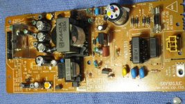
Whole view of PSB
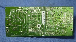
Underside, flipped horizontally from above pic.
I doubt there's any issues beyond the main transformer, I would think that when Z101 failed, it opened the fuse. It would take more than a split second to burn out windings or a cap, and the only IC on the board is near the end of the circuit. I suppose the only way to test that would be to get it working to see if woks or not.
I pulled the power supply out of another 525, swapping out the board gets the unit working as it should, so the damage didn't extend beyond the psb.
Oddly enough though the other unit has a slighty different layout, but the same number on the board
The gray varistor shows super high resistance, or open.
I didn't go any further than just plugging it in and seeing if it worked but it plays a cd, ejects, and turns on and off.
I returned that board to the other player and put it back into its cabinet.
With out the proper resistance on the power leads, it must have cooked the windings in the small transformer after C101.

Whole view of PSB

Underside, flipped horizontally from above pic.
With the bridge removed make sure these caps are OK and also that resistor. C101 would be favourite. They may not read short on a DVM but could fail when voltage is applied.
You can remove and link out L101 as a test. It is a 'common mode choke' just to prevent interference escaping for the PSU back to the mains.
Also if you use a low wattage DBT it will save all your fuses 😉 and also let you measure voltages and see where any problem is.

You can remove and link out L101 as a test. It is a 'common mode choke' just to prevent interference escaping for the PSU back to the mains.
Also if you use a low wattage DBT it will save all your fuses 😉 and also let you measure voltages and see where any problem is.
The manual give no voltages, other than the final output, which I believe is 27v on the high side.
With the varistor removed, won't the input voltage at the diodes be higher than expected?
If I remove L101, the short is gone, if I jump it, the short is gone.
I have a DBT but I've been using it with a 60w bulb. it lights the bulb but sill blew the 2a fuse. I didn't think to try a lower watt bulb I guess. What I don't see is how that choke is shorted, it should have no direct cross to the opposite pole, its a hollow core with four loops of enameled wire.
Wouldn't or shouldn't the presence of R101 and Z101 reduce the input voltage that eventually reaches the rectifier?
With the DBT, the bulb lit very slowly, then blew the fuse. C103 and C104 are removed right now as are the diodes, which all test fine. What I can't test is the IC .
Is it odd that they rectify the power before the transformer?
- Home
- Source & Line
- Digital Source
- Pioneer DV-525 DVD player failed while turned off?