greetings everyone...
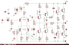
I saw this schema on the net and was said to be from pioneer...
would it be nice to DIY...what do you think of this?...
if not, what changes should i do to make it work?...
comments and suggestions highly appreciated...
regards,
ees
I saw this schema on the net and was said to be from pioneer...
would it be nice to DIY...what do you think of this?...
if not, what changes should i do to make it work?...
comments and suggestions highly appreciated...
regards,
ees
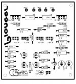
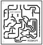
Attachments
First.
+/-70 Volt looks way too much for 1 Pair output devices.
Make it +/-40 or +/-50
Second.
I would add one transistor VBE multiplier
instead of them two 1N4148 in middle.
Otherwise the schematic is very nice. It could work well.
+/-70 Volt looks way too much for 1 Pair output devices.
Make it +/-40 or +/-50
Second.
I would add one transistor VBE multiplier
instead of them two 1N4148 in middle.
Otherwise the schematic is very nice. It could work well.
First.
+/-70 Volt looks way too much for 1 Pair output devices.
Make it +/-40 or +/-50
.
wll +/-70v wont be too much f i add 3 more pairs of output devices???...
what other changes/mods shall i do for the amp to face higher voltage???...say +/-90v...
any way here is the site from which i got the schema...
Pioneer stereo amplifier circuit with A733 – Free Electronic Circuit Schematics
regards,
ees
pwede kaya +-91 volts ang ilalagay natin supply para dito mga bossing.. ano kaya pwede e modify natin para dito para kayanin ang +-91 voltsmga master......
pwede kaya +-91 volts ang ilalagay natin supply para dito mga bossing.. ano kaya pwede e modify natin para dito para kayanin ang +-91 voltsmga master......

English only please as per the rules.
http://www.diyaudio.com/forums/site-announcements/167561-diyaudio-rules.html
(I can't even come up with a translation for that)
Why start with a simple, low power design and try to whoop it up to hundreds of watts with a few dodgy mods?wll +/-70v wont be too much f i add 3 more pairs of output devices???...
what other changes/mods shall i do for the amp to face higher voltage???...say +/-90v...
There a dozens of high power designs, some similar to this Hitachi balanced VAS design from thirty or more years ago, which have been designed to work with higher rail voltages right from the beginning, as they should be. Don't start projects with untested, heavy modifications as you will likely have difficulties getting the best, if any performance from it, if you are still learning how to to go about design, as you build.
If you think the low cost parts in the Pioneer circuit will remain simple and cheap when you have properly converted it to 90V rails, for example, it won't be. The cost will be the same for equivalent power, of other high power amplifiers, so start right with one of Apex's designs or one of the higher power Symasym designs which use similar topology, if you want lots of power. Just don't assume high voltages and more output transistors is enough to make a successful, high power amplifier from a low power one.
Is there something wrong with setting out your design's power output and choosing a known working design to suit that in the first place?
It may not be obvious to everyone but a lot Japanese amplifiers in the 1980s used high rail voltages, but puny transformers which saved money and provided SOA limiting for the ouput stage at the same time. They worked well and saved a lot of failures due to clumsy use, even with shorted leads and abuse. If a normal, high current or "stiff" supply was used , the single pair of output transistors would have soon failed. So, a 70V nominal supply is probably down to around 50V when the peak allowable current demand occurs. That makes it a kind of power limiting circuit. Even so, an 8R/4R switch was often used to lower the transformer voltage to suit lower rail voltages at 4R loads.
What I'm saying here, is that rail voltages on schematics have to be understood in reference to the available current. Assume nothing! 😉
ok sir i'm sorry for that,, what i mean is this amplifier can handle -+91 volts this pioneer using a733,??
sir i have a transformer of 65-0-65 ac,, is it ok to supply this pioneer amplifer or this too high for this amplifer..
Hi eper puliran
Perhaps you misunderstood the earlier posts. Let me be clear - No, you cannot power this design with your transformer!
A safe maximum for a single pair of output transistors, as the OP design specifies, would be even less than the +/- 70V supply rails specified. 70V rails suggest an output of 250W/8R which is far beyond the capability of even the big MT200 cased 2SC3858/A1494 transistor pair.
HTTP 301 This page has been moved
You are asking if a transformer that produces rectified DC rails of +/- 90V will be ok? Please use some common sense. You can add as many pairs of output transistors as you like but the final result will be poor if the amplifier is not designed to drive them with sufficient voltage and current gain. To utilise (+/-90V rails, you need to construct a very big and expensive power amplifier of perhaps 450W/8R. You would do all that just to try a simple, low cost design meant for only 30 -50W?
However, if you really do want a high power amplifier, this design is definitely not suitable. Read lineup's comments, post #2 for appropriate DC rail voltage for use with these low voltage transistors. Again - No, your transformer voltage is far too high - you require only 25-35VAC secondary windings.
To be honest, if you have to ask "is this design OK for 90v" then really, you should not be building an amplifier with such high voltages. That is 180v between supplies, which can be lethal.
- Status
- Not open for further replies.
- Home
- Amplifiers
- Solid State
- PIONEER A733