I have a a400 which has stopped working powers on but no relay click. The output transistors have tested ok with my component tester yet when i re solder them back in they read 41-42volt dc on all3 pins with negative lead of meter grounded to case! Is this right or are the output transistors gone? There's a lot of talk about this problem on the net but cant find a solution any help will be appreciated thanks glenn.
There are two output transistors per channel. So you have to determine if one or both channels are faulty. The outputs may or may not be faulty although a usual failure mode would be short circuit C-E.
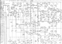
Look at circuit and locate the 0.33Ω emitter resistors connected to the output transistors. With the amp off measure and confirm these are OK.
To help determine if one or both channels are faulty measure the DC voltage at the junction of these resistors with the amp on. It should be around zero. This is the speaker output from before the speaker relay.
Favourite suspects would be output transistor, maybe the drivers and the 0.33Ω.
Also check the 4.7Ω base feed resistors and the four 100Ω resistors that feed the bases of the driver and pre driver transistors.
Careful voltage checks would definitely reveal the problem though.
Hi thank you for the reply. I have checked all otput and driver trans and all ok the risistors are ok the emitter ceramic ones measure 1 ohm across outside pins and 0.7 to the center pin across the emitter risistors measures 14 mv on one side and zero on the other.
In post #1 you say there is 40+ volts on all 3 legs of output transistors/s ?
Which output transistor or transistors have this 40 volts on all three legs ? Whichever that is, that voltage must also be present on the 0.33Ω in that channel as these connect to the emitters.
It would be unusual for both channels to be faulty but check the voltages on all four outputs and record and post the readings for each lead. So thats 12 readings.
Hi with a volt meter set to dc volts and negative lead to the case of the amp the reading are as follows the left channel 2SA1302 E - 41.2 C - 44.6 B - 41.4 2SC3281 E - 41.3 C + 44.6 B - 40.5 .
The right channel 2SC3281 E - 41.7 C +44.8 B - 42.0 2SA1302 E - 41.6 C - 44.4 B - 42.1 .
The reading on the emitter risistor set on dc and measured across the 2 outer pins are left channel is 14 mv and zero on the right cheers glenn.
The right channel 2SC3281 E - 41.7 C +44.8 B - 42.0 2SA1302 E - 41.6 C - 44.4 B - 42.1 .
The reading on the emitter risistor set on dc and measured across the 2 outer pins are left channel is 14 mv and zero on the right cheers glenn.
I'd go long with RJM1's suggestion.
Your readings point to a common factor affecting both channels. Q237 appears to be drawn incorrectly on the diagram... it's an NPN device. There are some other errors there too, rails going to the wrong regulators and reversed caps.
Check for 40 volts or so on the emitter of Q237
Your readings point to a common factor affecting both channels. Q237 appears to be drawn incorrectly on the diagram... it's an NPN device. There are some other errors there too, rails going to the wrong regulators and reversed caps.
Check for 40 volts or so on the emitter of Q237
Hi i have removed and tested q 237 & q238 and the 4 risistors all ok the emitter of q 237 is 44.4 and q 23 is - 44.3 .
I have just found a faulty trans on the left channel q205 2SA1048 which has gone short circuit emitter to base. I have tested the same one on the right side which tested ok. Orderd some replacement trans on ebay a few quid for 5. I am hoping this is the problem? Any ideas guys..
That's a strange failure mode... but if it is short circuit (and you must measure with it removed from PCB), then it's a start.
I think there is more to this though as it would only account for one channel not working. Although the speaker relay is common to both the DC conditions on the "good" channel would be correct and they are not, you have -40 volts on the emitters of all the outputs.
Has this amp some history ? Was it being modded etc or did it just fail in use ?
Hi the amp was bought off ebay with a faulty vol pot broken carbon track on one side which i replaced with a 3 pin pot without the balance tap it worked for a a while then stopped working . The measurements on the output trans was made with a meter on dc volts with the negative lead to OV amp case is this the correct way? .
Hi Glenn. Yes that's the correct way to measure the voltages. If the volume control was broken is it possible the amp has other damage such as cracked print somewhere.
The secret to fixing this is going to be in careful voltage measurements and perhaps working on and fixing one channel at a time.
The secret to fixing this is going to be in careful voltage measurements and perhaps working on and fixing one channel at a time.
Today i have removed all the transistors diodes from board and tested i have found 4 faulty transistors they are q203 q204 q205 q215 all 2SC1048 trans 203 & 204 short on all pins trans 205 & 215 emitter and base short circuit. I am wondering if its wise to test the 6 transistors in the phono stage or not before replacing the 4 faulty transistors and powering up.
Hi Glen, the most important thing is to put the amp in as safe as possible state to minimise damage if there is a problem.
That means a bulb tester... a 100 watt filamant bulb in series with the mains supply. If there is a fault and the output stage draws excess current then hopefully it protects the outputs.
I would work on one channel at a time.
No need to do any checks in the phono stage at this point.
That means a bulb tester... a 100 watt filamant bulb in series with the mains supply. If there is a fault and the output stage draws excess current then hopefully it protects the outputs.
I would work on one channel at a time.
No need to do any checks in the phono stage at this point.
Just quickly looked at the circuit again... Q205 as an example. That is a PNP type (marked 2SA1048), not a 2SC1048
Any device marked 2SC are NPN and 2SA are PNP
Something drastic has happened to this amp I think.
Any device marked 2SC are NPN and 2SA are PNP
Something drastic has happened to this amp I think.
hi mooly just had a look at my other A400 which is working and the 4 transistors in that amp are the same as the one's i pulled out of the bad amp yesterday ?.
looks like the circuit diagram is wrong ! the 4 transistors all have A1048 on them .
looks like the circuit diagram is wrong ! the 4 transistors all have A1048 on them .
- Status
- Not open for further replies.
- Home
- Amplifiers
- Solid State
- Pioneer A400 problem