Hi to all,
I have a Parasound D/AC-1500, running four PCM63K, the second pair is only used for XLR output. In short, two complete Stereo Dacs in one cabinet.
Using only RCA outputs, I would like to mod the second DAC with pcm1704.
The Parasound has been already upgraded with a DF1704, since yesterday
a DF1706, providing 24 bit output and running in parallel with the DF1704 has been already installed.
Now my question:
Can I pggyback two pcm1704 for gaining the same current output as the pcm63? I´ll have to use adaptor boards anyway, so I could also parallel them using the sourroundin caps/electronics needed for each PCM1704.
Is paralleling/piggybacking a wise step or useless, as long as you do not invert the second DAC and sum the currents using an opamp?
All the best, salar
Piggyback will (theoretically) improve by 3dB the signal/noise ratio. But it is better to do the summation after the OpApm filters, so that OpAmp noise will too be cut by 3dB (that of course means doubling the parts).
So, no problems when soldering the two current outputs together?
The output current is 1.2mA and the output impedance is 1kohm, will the output impedance stay the same, but
the current double?
BTW, output current of the PCM63 2 mA, output impedance is 670 ohm. The opamp connected to the PCM63 output is an AD841.
All the best, Salar
The output current is 1.2mA and the output impedance is 1kohm, will the output impedance stay the same, but
the current double?
BTW, output current of the PCM63 2 mA, output impedance is 670 ohm. The opamp connected to the PCM63 output is an AD841.
All the best, Salar
Last edited:
O.k, it can be done. Stumbled over the PCM1702 evaluation board which allows up to 4 PCM1702 per channel.
But now I need help from you guys in calculating the feedback resistor and capacitor in I/V stage.
A formula is given for calculating the I/V conversion for paralleled DACS in the PCM1702 Evaluation board´s Datasheet,
but i was always v e r y bad in mathematics. BTW, output current and impedance of the PCM1702 and pcm1704 are the same.
So here is the math:
DAC current output of the original PCM 63 is +-2mA
Output impedance is 670 ohm
The PCM63 has already a built in 1.5kohms feedback resistor for I/V conversion. Parasound chose this resistor for the circuitry and added a 1000pF capacitor.
The following opamp is AD841.
Now I have TWO PCM1704 replacing ONE PCM63.
The PCM1704 has an output current of +-1.2mA, output impedance 1kOhm.
What resistor value and capacitor value do I need to get the same voltage output of AD841 for those two 2 PCM1704 replacing one PCM63?
Would also be intersting for listening purposes to match them to get the same output voltage. As I wrote,
there are two complete Stereo DAC boards in the Parasound D/AC 1500,
the second additionally used for XLR output. (Phase Inversion is done digitally, IC can be easily removed and bypassed) So my mod will result in two complete PCM63 and PCM1704 Dacs...
Thanks in advance,
all the best, Salar (soldering now for two days)
Last edited:
There are 2 ways:
1. tie toghether all the resistor terminals of the DAC's and to one OpAmp. You need to choose an OpAmp capable of driving the total ammount of current (from all DAC's). Or add a buffer after the OpAmp output (like BUF). For example LM4562 can drive max +/-23mA. OP275 can do 38mA.
2. use one OpAmp per DAC as per datashet and mix (add) all the voltage outputs with one output OpAmp buffer.
PS: When you parallel two sources, the resulting current doubles, while the internal voltage remains the same - therefore the equivalent output impedance halves (ohms law).
Last edited:
Hello SoNic_real_one,
thanks for the hints, but I do not want to change the existing opamps.The PCM1704 has no resistor teminals (whereas the pcm63 has resistor terminals.)
In the PCM17032 evaluation board, the current output of the dacs is mixed and fed to one opamp.
So, I need to calculate the resistor value for +-2.4mA (PCM1704) in relation to the original +-2ma of the pcm63?
So the resistor for two PCM1704 will need 3.2kohm, or am I wrong here?
Impedance will be 500 ohm?
All the best,
Salar
For two, the impedance will be 500 ohm (+/-2.4mA).
The application from the catalog shows a 2.5kohm conversion resistor in the I/V stage - to make 2.4mA x 2.5k ohm = 6Vpp = 4.24Vrms. The filter stage I think leaves 2.12Vrms at the output.
For your two parallel DAC's you will have to divide the 2.5kohm by 2 = 1250 ohm.
Mind that the OpAmp output current will double too (+/-5mA).
Hello SoNic_real_one,
thanks!
The orignal PCM63 had +-2ma, so the output current of the opamp was 4mA?
I am too dumb to draw conclusions from the AD841 darasheet, but as I understand, the maximum output current allowed is 50mA (nothing written about the max. input current anywhere...)
All the best,
Salar
thanks!
The orignal PCM63 had +-2ma, so the output current of the opamp was 4mA?
I am too dumb to draw conclusions from the AD841 darasheet, but as I understand, the maximum output current allowed is 50mA (nothing written about the max. input current anywhere...)
All the best,
Salar
The output current of the OpAmp is what I am talking about. That's what drives curents into the virtual ground, not the input.
AD841 has 50mA but... is good for video apps, not for audio.
AD841 has 50mA but... is good for video apps, not for audio.
why you need this? 1704 is worst compared to 63Can I pggyback two pcm1704 for gaining the same current output as the pcm63?
Hi
Can you explain this? Why is 63 better?
Can you explain this? Why is 63 better?
1704 is worst compared to 63
So, finished my mod yesterday. Kudos to BB-Ti, my esd-protective workplace consisted in tieing myself, soldering iron and the IC´s to the central heating of my home. I had to use simple adaptor boards, solder every cap directly on the pins. I had a simple copper sheet glued beneath the adaptor boards as ground plane. The IC´s were heated VERY often during soldering but they survived.
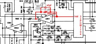
First I thought I grilled half of them, because signal level was too low after I/V conversion, but I found the value of the cap bypassing the I/V resistor was too high. So now I have two PCM1704 per channel, each with its own caps, current outputs connected together, using a 2500ohm resistor with a 47pF cap to get - almost - the same signal level as the PCM63.
The PCM63 provides 4mA current, sent via a 1500 ohm built in resistor and 1000pF bypassing cap. (Around 6V unbalanced line level! Newer amps using IC for volume control will clip)
The two PCM1704 provide 2.4mA.
There is still a slight mismatch in volume between the original PCM63 board and the modified PCM1704 board, so it is not easy to judge the benefit of the mod. The PCM-1704 board is a bit louder.
Maybe someone can help me in calculating the bypassing cap for I/V conversion to match volumes between the two boards?
Again, the values:
PCM63 - 4mA, 1500ohm, 1000pF
2x PCM1704 2,4 mA, 2500ohm, 47pF
Opamp for I/V conversion in both boards is AD841.
In the moment, the PCM1704 - modified board is a bit louder.
Using a 1000pF cap on the 2500ohm resistor (in fact 4x10Kohm) lowers the
voliume to 1/4. So I sticked with the 47pF cap in the PCM 1704 datasheet. But maybe this value has to be changed?
All the best,
Salar
Last edited:
What is already audible: a -60dB 1kHz sine wave from a 16 bit source shows lesser sawtooth artifacts on PCM1704 than on PCM63.why you need this? 1704 is worst compared to 63
But I have to use two digital filters, DF1704 for PCM63, DF1706 for PCM1704.
But I guess the filters do not make much of a difference.
What are saying makes no sense. The capacitor over I/V resistor shouldn't affect the volume level, it is there to cut the ultrasounds - only eventually the high frequency response if it is to big.
Rather, when you changed that capacitor, you repaired a bad solder on the OpAmp.
Rather, when you changed that capacitor, you repaired a bad solder on the OpAmp.
much better sound, better reference, MSB bit adjustment,in practice less distortion, more current, etc etc etc 1702/1704 is only low coast version of 63Can you explain this? Why is 63 better?
in terms of sound quality, filtering precision 1704/1706 is one of the worst DF for 20-24bit dacs ever madeBut I guess the filters do not make much of a difference.
What are saying makes no sense. The capacitor over I/V resistor shouldn't affect the volume level, it is there to cut the ultrasounds - only eventually the high frequency response if it is to big.
Rather, when you changed that capacitor, you repaired a bad solder on the OpAmp.
No, I can repeat the effect. 1000pF over 2500ohm result
in lower volume. I did not measure at the resistor, just line out jacks.
The output of opamp (AD841)for I/V conversion is connected to the analog filter using a 1000ohm resistor. I will post part o the schematic tomorrow.
much better sound, better reference, MSB bit adjustment,in practice less distortion, more current, etc etc etc 1702/1704 is only low coast version of 63
As I said: a simple -60dB 1KHZ sine wave is lesser distorted on the 24 bit pcm1704 than on a 20 bit PCM63. Wether it is the digital filter or the dac making 24bit dithering possible, I do not care. The PCM63 sounds snappier, one has to like it. Ever listened to orchestral music Gyan Kancheli? Most of the time an orchestra playing arund -25 to -35 db, with sudden outburst to full scale. Not very suited for pure 16bit resolution
in terms of sound quality, filtering precision 1704/1706 is one of the worst DF for 20-24bit dacs ever made
Make a proposal a mere mortal can get and that is running without a controller.
Last edited:
2500 ohms with 1000pF should give a corner frequency of 64kHz. If you hear "lower volume" something is not right... Maybe you have read wrong the capacitor value.
StrangeAs I said: a simple -60dB 1KHZ sine wave is lesser distorted on the 24 bit pcm1704 than on a 20 bit PCM63
And 1702\04 has worse reference thats why he has more signal dependent output noise(+much signal dependent distortion becouse of its architecture) -> more coloration of sound
PMD100, SM5842, SM5847Make a proposal a mere mortal can get and that is running without a controller.
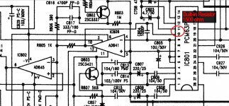
O.K, here are the circuits, original and modified.
I made a mistake in the left drawing: The original buit-in resistor 1500 ohm is between pins 9 and 10
As I wrote, keeping the original capacitor C804 1000pF in the modified circuit will lower the volume to 1/4th. I did now put in 47pF, but there must be a reason why Parasound put 1000pF. (in the PCM63 Datasheet´s circuit example, no paralleled cap is mentioned) So I would like to put in a capacitor with higher value than 47pF and appreciate advice on this. Maybe R805 has to be replaced as well?
Thanks a lot,
Salar
Attachments
Last edited:
- Status
- Not open for further replies.
- Home
- Source & Line
- Digital Line Level
- "Piggybacked" PCM1704