I am just wondering if there is anybody here that has had this issue with their circuits. Also how likely is it that this effect will add distortion/noise to the output of an amplifier even if it is not used in the audio path but only for decoupling purposes of MOSFETS, op amps, and also used as power supply capacitors.
Kemet claims that their KPS series of ceramic capacitors significantly reduces this piezoelectric effect. Does anobody have experience with this?
Kemet claims that their KPS series of ceramic capacitors significantly reduces this piezoelectric effect. Does anobody have experience with this?
Ever since I started tinkering with audio circuits I've used ceramics liberally (to say the least) in pretty much everything I've built. I've never once heard a "singing capacitor". Either I'm extremely deaf, or it's not that big of deal.
I know a lot of the things I've built probably would have been oscillation nightmares without the use of ceramics. Maybe some still were, I don't own a scope. 😛
I would say just use C0G if you can, then quality X7R if you need a higher value. Stay away from Y5V completely.
Have a look at these ceramic nightmares...
An externally hosted image should be here but it was not working when we last tested it.
An externally hosted image should be here but it was not working when we last tested it.
The Class-D amplifier I just designed has the piezo effect for sure every time I do a sweep and the frequency goes above 2k at full power you hear it. But will the piezo effect actually add distortion to the amplifier is my question? I ask this because also right around 2k the distortion starts to go up.
I know that C0G does not exhibit the piezo effect. Unfortunately I cannot get the capacitance that I need in with C0G in any kind of manageable size or cost.
I am getting some caps from that Kemet series that I mentioned earlier to try, they are not cheap at least they are available in the same size and value that I already have on the PCB.
The Class-D amplifier I just designed has the piezo effect for sure every time I do a sweep and the frequency goes above 2k at full power you hear it.
What function do the "singing caps" caps serve in your circuit?
I am getting some caps from that Kemet series that I mentioned earlier to try, they are not cheap at least they are available in the same size and value that I already have on the PCB.
I'm notoriously cheap; I would probably do a poor mans version of those if I though I needed them. Double stack some X7R caps with a small gap between them and then solder some small leads to the end to use as "stand-offs" so it doesn't touch the PCB. Maybe even coat them in some hot glue (if they don't get hot in their application) or some non-corrosive silicone adhesive.
I've certainly heard singing caps, and not just ceramics. IMO, if it's a bypass I doubt microphonics/piezoelectrics matter at all. I'd never use anything but an NP0/C0G in the signal circuits. The very best caps I've ever measured were the Corning "Spinguard" NP0 caps. Small green or gold bodies, up to 0.01 uF, near zero dissipation factor and temperature stability so good you couldn't measure it. I don't know if anything like them is still available.
Piezoelectric effect is reversible: capacitors not only "sing" by applying AC voltage, but worse than that, they generate a pulse by hitting them. I experienced (and heard through the loudspeakers!) this effect by hitting a tantalum filter capacitor at the power supply of a DAC chip. Since then I test all capacitors in the actual circuit by hitting them with the grip of a screwdriver. BTW cables also have this behavior.
Ceramics in bypass situations are not gonna cause any problems, they are used in nearly all circuits out there not just audio, but in high rel circuits where such things can be very critical.
Got some scope shots, where are the caps being used in the circuit. Though SMPS and therefore class D are probably the best circuits for getting caps singing.The Class-D amplifier I just designed has the piezo effect for sure every time I do a sweep and the frequency goes above 2k at full power you hear it.
Piezoelectric effect is reversible: capacitors not only "sing" by applying AC voltage, but worse than that, they generate a pulse by hitting them. I experienced (and heard through the loudspeakers!) this effect by hitting a tantalum filter capacitor at the power supply of a DAC chip. Since then I test all capacitors in the actual circuit by hitting them with the grip of a screwdriver. BTW cables also have this behavior.
!!!!!!!!!!!!! Not exactly a real life situation, its rather extreme hitting the device, this is well known and well documented, but even on high vibration resistant designs you cannot generate the same level during vibration testing as you get by a direct force to the device, it is not relevant in real circuits unless you use your PCBs as drums.
Film type capacitors do this too. Take your ordinary 100+ watt class AB amplifier, and drive it to severe clipping without a load. Listen to the output zobel - you'll swear that capacitor is going to explode. Class D filters and class H commutator snubbers are also subject to these high frequency loaded transiets and the caps can also make noise. Doesn't matter if they are ceramic, MKP, or some lesser mylar grade.
It's a good thing most SMPSs use switching frequencies above 20k - or the noises from all the trafos and caps would be driving everybody crazy. Like the incessant 15.75k from CRT monitors used to.
It's a good thing most SMPSs use switching frequencies above 20k - or the noises from all the trafos and caps would be driving everybody crazy. Like the incessant 15.75k from CRT monitors used to.
I experienced (and heard through the loudspeakers!) this effect by hitting a tantalum filter capacitor at the power supply of a DAC chip.
Tantalum capacitors are not piezoelectric. (As far as I know.)
Do you know otherwise ?
Since another poster talks about hearing a sound from hitting film capacitors, it must be some other physical phenomenon ? Or perhaps even a dry solder joint ?
Last edited:
Ceramics in bypass situations are not gonna cause any problems, they are used in nearly all circuits out there not just audio, but in high rel circuits where such things can be very critical.
Got some scope shots, where are the caps being used in the circuit. Though SMPS and therefore class D are probably the best circuits for getting caps singing.
The capacitors are being used to decouple the switching MOSFETS for the H-bridge. That is the highest current area. I have them in other places in the board but i doubt the ripple current in those locations would be large enough to cause this piezo effect.
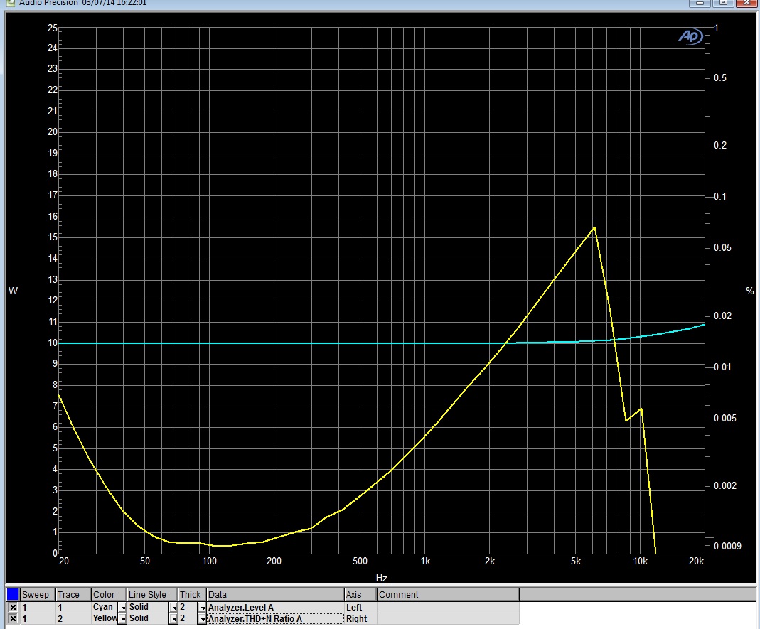
In this image you can see the distortion of the class-d amplifier rises sharply and peaks at around 6khz. I am wondering how much of this is if any is caused by the piezo effect. Since I took that image I have been able to modify the modulator such that the peak is now at around .01% THD but I cannot seem to be able to get the peak any lower. This is why the quesion about piezo effect causing the distortion.
Hitting a component on a PCB is not a good idea or something an assembly is subject to in real life (apart from ballistic tests, which don't apply to domestic hi-fi gear). The main reason is the focused applied shock, this will cause quite a severe wave to propagate through the PCB stressing abnormally solder joints and in the case of SMD components their own integrity. Especially multi layer ceramic capacitors and other leadless SMD components.
Now while your all thinking SMD bad PTH good, ask your selves why PTH electrolytic caps. have either some silicone or other form of damping applied...differential vibration, one of the reasons why in old guitar amps there always a resistor mounted of the board that has a dry joint. The compliant lead of PTH components allows them to vibrate at a different rate from the PCB, this puts stress on the solder joint and on simple single or double layer PCBs this can cause the joint to fail due to prolonged vibrational stress. While SMD can be prone to excessive applied force, most modern day components have no leads or very small ones and vibrate in phase with the PCB exerting very little stress on the solder joint. Better still are assemblies with components built into the PCB, apply some gunge and it becomes one homogenous mass.
This is for space saving but think of the applications in really high vibrational situations.
🙂
Stress changes the capacitance. If there is a dc voltage on the capacitor, charge is stored. Changing C while charge Q is conserved causes V to change ie an ac signal is generated.Since another poster talks about hearing a sound from hitting film capacitors, it must be some other physical phenomenon ? Or perhaps even a dry solder joint ?
The capacitor acts as a condensor microphone
It was definitely not due to dry solder joint. When I replaced the tantalum to polypropylene the effect has gone. I don't like when my components are acting as a microphone.Tantalum capacitors are not piezoelectric. (As far as I know.)
Do you know otherwise ?
Since another poster talks about hearing a sound from hitting film capacitors, it must be some other physical phenomenon ? Or perhaps even a dry solder joint ?
Strange since tantalum caps are not microphonic...
But then hitting components with a screwdriver is stupid...so it must even out.
But then hitting components with a screwdriver is stupid...so it must even out.
I tried using some 10uF X7Rs in an ICL7660 negative rail charge pump. They sang for sure (around 10kHz), I replaced them with electrolytics and all was fine.
If they generate electric signal by mechanical excitation, they must alter the sound by exciting them acoustically (i.e. acoustic feedback), that was the rationale behind my test.Strange since tantalum caps are not microphonic...
But then hitting components with a screwdriver is stupid...so it must even out.
Would you put an acoustically sensitive capacitor in a crossover?
I am aware of how components behave under vibration (but not on domestic music reproduction, just more mundane things....🙂) as I stated earlier, I also posted a long reply on why hitting the components is not a good idea #12...
As mentioned above you don't even need piezoelectrics- all caps develop forces between the plates.
F=(AEV^2)/(2S^2) Newtons, where A is the area in meters^2, E is 8.85E-12 times the dielectric constant of the material in use, V is the voltage and S is the electrode spacing in meters.
F=(AEV^2)/(2S^2) Newtons, where A is the area in meters^2, E is 8.85E-12 times the dielectric constant of the material in use, V is the voltage and S is the electrode spacing in meters.
Its not over till the Fat Cap Sings....
http://product.tdk.com/capacitor/mlcc/en/faq/pdf/31_singing_capacitors_piezoelectric_effect.pdf
http://product.tdk.com/capacitor/mlcc/en/faq/pdf/31_singing_capacitors_piezoelectric_effect.pdf
- Status
- Not open for further replies.
- Home
- Design & Build
- Parts
- Piezoelectric Effect of Ceramic Capacitors