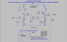
Hello and thanks for showing up. I've built a tube phono preamp using 5842s from a circuit by Joe Tritschler. It functions, but in use, the RIAA EQ is out of whack. The LFs are heavily attenuated, but other than that it sounds very good, quiet and clear. Testing showed the LED bias doesn't seem right and I'm pulling 8.3mA at the plates instead of the 15mA the design specifies. I'm also unsure about my 6.3V filament wiring. I've wired +6.3VDC to pins 3 and 0VDC to pins 9 (I know I didn't have to twist the heater wires, it's just force of habit). Can anyone point out any mistakes? The LED is the one specified in the article (https://audioxpress.com/article/borbely-riaa-preamp-with-tubes-project-remembered-and-revisited) should I try a different part? Attached is the schematic with specified voltages (mine are red) and a picture of the circuit as built.


The operating points are so different that the RIAA could be significantly altered.
A different brand of tubes could help. Have you measured the response?
The 4V on a red LED does not seem right at all, in fact that's physically impossible.
Do both LEDs measure 4V? Check the LED polarity carefully. Does it light up?
Also, does your meter measure a 1.56VDC alkaline battery correctly?
Last edited:
There is certainly something very wring with the second tube. It's either a blown/reversed led, a missing grid leak resistor or something equally obvious.
The active second part of the correction is a lot more fussy with respect to the operating point . As Rayma mentioned this is enough to mess up the frequency response.
The active second part of the correction is a lot more fussy with respect to the operating point . As Rayma mentioned this is enough to mess up the frequency response.
Perhaps unrelated to the issue at hand but the 5842 is not the easiest tube. I like to make use of all those grid pins and not leave them unconnected. There is no grid stopper for the second stage. I am also uncertain if there are any power supply decoupling caps on that chassis, there should be.
Following up on analog_sa's comments on the 5842, I note that Tritschler uses 6922s in his commercial version.
New Energizer Max at 1.6177. Might be a problem, but is it that much?The operating points are so different that the RIAA could be significantly altered.
A different brand of tubes could help. Have you measured the response?
The 4V on a red LED does not seem right at all, in fact that's physically impossible.
Do both LEDs measure 4V? Check the LED polarity carefully. Does it light up?
Also, does your meter measure a 1.56VDC alkaline battery correctly?
All 4 LEDs measure in that same range, All light up, Cathode (flat) to ground
I know about physically impossible, I've killed two early eighties Volvos and a 5.0 302. I'm a pro.
Tubes are matched Amperex (FWIW)
Suggest you determine why the LEDs measure 4V instead of 2V. That's importantNew Energizer Max at 1.6177. Might be a problem, but is it that much?
All 4 LEDs measure in that same range, All light up, Cathode (flat) to ground
I know about physically impossible, I've killed two early eighties Volvos and a 5.0 302. I'm a pro.
Tubes are matched Amperex (FWIW)
because they bias the tubes very differently than the design requires.
Good to know about the tubes. Thank you.Perhaps unrelated to the issue at hand but the 5842 is not the easiest tube. I like to make use of all those grid pins and not leave them unconnected. There is no grid stopper for the second stage. I am also uncertain if there are any power supply decoupling caps on that chassis, there should be.
How would you make use of the pins? I wondered if they should all have been tied together initially. I'd never worked with them before.
I didn't realize there was a commercial version. Thanks for the heads up.Following up on analog_sa's comments on the 5842, I note that Tritschler uses 6922s in his commercial version.
Those are very different tubes.I didn't realize there was a commercial version. Thanks for the heads up.
You must have a wiring error somewhere. I ran a simulation and got voltage and current values close to those shown in the schematic (see attached). The SPICE model I used for the 5842 tube can be found here in the triode-nh.txt file.
https://www.intactaudio.com/forum/viewtopic.php?t=526
https://www.intactaudio.com/forum/viewtopic.php?t=526
Attachments
Good idea, what else could it be? Math says it's about 240R.Could you tell us what LED's you bought. You can bug some with built in resistor.
Last edited:
Sorry I updated my comment. Anyway put one across a bench supply with resistor and measure. You can buy 5V and 12V ones and they look just the same.
Last edited:
Thanks for running that, what are the specs on the LED used to model? I am thinking that my problem lies there. Not to say i didn't miswire or there's some other mechanical problem.You must have a wiring error somewhere. I ran a simulation and got voltage and current values close to those shown in the schematic (see attached). The SPICE model I used for the 5842 tube can be found here in the triode-nh.txt file.
https://www.intactaudio.com/forum/viewtopic.php?t=526
For purposes of a test, just patch in any (different) red LED that you have lying around,
for just one tube section of one channel. If the bias voltage goes to 2V instead of 4V,
as it should, then that's your problem.
for just one tube section of one channel. If the bias voltage goes to 2V instead of 4V,
as it should, then that's your problem.
Unfortunately, I built this a while ago and just recently got the funds for the tubes, so I might not be able to locate one of the same LEDs. They are easier to identify because they are larger by a margin than standard cheap-os. I was diligent in my ordering though to get the ones specified in the article, baring a fat finger mistake. I'll dig for a minute and see what I can find. Thanks for the advice.Sorry I updated my comment. Anyway put one across a bench supply with resistor and measure. You can buy 5V and 12V ones and they look just the same.
- Home
- Amplifiers
- Tubes / Valves
- Phono Preamp Misbehaving