OK this is a common situation, nice tube phono pre-amp, nice tube amp, perhaps we can eliminate the pre-amp's cathode follower?
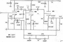
I have arriving PCBs with the following schematics (see attachments), one is for MM only, the other is for MC or MM.
Now the tube amp I have to feed is the Sweet Peach FU50 which has an input impedance of about 100k (this will be 'arranged' for phono input).
For my MC cartridge (Ortofon MC20 sII) needs to step up about 10X gain, so I was thinking of a cunning plan.....
Looking at the (left hand) 3 triode MM schematic (2 + CF buffer) I was thinking if I convert the cathode follower to a 10x gain stage it would a) be ok for MC, b) reduce the filament/cathode voltage and c) convert the CF buffer.
However the NFB EQ would now be the wrong polarity (PFB!) and 10x too big, so can anyone suggest a simple change to make that work?
Also any ideas on the plate and cathode resistors for 10x gain for that tube?
Oh - and views on my cunning plan please 😉
Attachments
However the NFB EQ would now be the wrong polarity (PFB!)
Apply feedback to inverting input instead ?
and 10x too big, so can anyone suggest a simple change to make that work?
Adjust feedback resistor accordingly ? (check out RDH chapter 7 for relevant formulae or use a multiurn potentiometer/rheostat in place of feedback resistor and tweak until you get the most swing without distortion)
Oh - and views on my cunning plan please 😉
I don't think it's as cunning as you think - 100K Zin of your amplifier will load the last stage and drastically change its operating point (all other things remaining equal as shown on left picture). That buffer stage is probably there for a reason.
I haven't had a look at the right picture so I cannot comment on it, your questions seem to refer to the left one anyway.
Thanks for the notes about the FB circuit, I'll look up the reference!
Ok so if the 100K Zin (or in fat the interconnect) is too much for a regular gain stage to drive, how about a variation on this idea for the final two triodes?
I'm not sure that would give enough gain however, but it may solve the cathode follower from being used.
I don't think it's as cunning as you think - 100K Zin of your amplifier will load the last stage and drastically change its operating point (all other things remaining equal as shown on left picture). That buffer stage is probably there for a reason.
Ok so if the 100K Zin (or in fat the interconnect) is too much for a regular gain stage to drive, how about a variation on this idea for the final two triodes?
I'm not sure that would give enough gain however, but it may solve the cathode follower from being used.
Perhaps not so cunning...
The noise figure of the tube at the input is not going to be low enough to provide very satisfactory snr - I would use that transformer and leave the rest of it as designed.
What you propose requires a legitimate redesign of the entire phono stage.
The noise figure of the tube at the input is not going to be low enough to provide very satisfactory snr - I would use that transformer and leave the rest of it as designed.
What you propose requires a legitimate redesign of the entire phono stage.
Why not exchange the input triode for a cascode with a few 2SK170s below and an E88CC on top? It will be a some work to redesign both input stage and EQ. Also I doubt noise will be low enough, though. About CF you could as well go sand.
As Kevin says, go for a SUT instead.
As Kevin says, go for a SUT instead.
Last edited:
Ok so if the 100K Zin (or in fat the interconnect) is too much for a regular gain stage to drive ...
Your picture shows common cathode stages with 270K anode load. 100K in parallel would change the parameters of operation significantly. This is what I meant above.
perhaps we can eliminate the pre-amp's cathode follower?
Why? For that sort of design, it's your only chance to ensure linearity, RIAA conformance, and avoid slewing as the output stage tries to drive the capacitive RIAA network. Granted, these are pretty poor cathode follower designs, but eliminating them will make a mediocre stage into a downright awful one.
Why? For that sort of design, it's your only chance to ensure linearity, RIAA conformance, and avoid slewing as the output stage tries to drive the capacitive RIAA network. Granted, these are pretty poor cathode follower designs, but eliminating them will make a mediocre stage into a downright awful one.
Hi,
Yes I've just been reading some of your posts regarding CFs, and it seems that as long as the cathode sits high enough above the ground the linearity is not too bad. So I will stick with the CF.
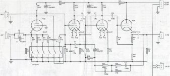
So... as I have an MC cartridge and no SUT I will end up using the 2nd all 12ax7 schematic (a populated PCB is on its way). I realise the S/N is not great but I do not think I can do much about that here.
....BUT I have heard that the AX7 makes a lousy CF stage (as used in the right hand MC schematic), and I have a drawer full of nice ECC88 tubes (BVC, Mullard etc). So I'd like to use the ecc88 in place of at least the final tube if not all of them - which means the final two triodes will be ecc88 rather than ax7.
First Q - is this a good idea?
Secondly:
So I have to modify the heater connection and the biasing - could you suggest any good values to use (i.e what changes for using ECC88s)?
Thanks for your time and expertise, much appreciated!!
Yes I've just been reading some of your posts regarding CFs, and it seems that as long as the cathode sits high enough above the ground the linearity is not too bad. So I will stick with the CF.
Necessary, but not sufficient. Here's a few other things to consider:
1. The tube- as you've surmised, a 12AX7 simply can't be made into a decent CF, no matter what. What you want is transconductance, making ECC88 (as an example) a far better choice.
2. The load- in order for a CF to have good linearity, the load has to be considered in the design. For a feedback RIAA stage, think about what happens at high frequencies when all of those capacitors have a low reactance... As a good first approximation, you can calculate what a tube's distortion will be if the load were in the plate circuit, then divide that by the gain when going to a CF configuration.
3. The operating point- this determines transconductance, distortion, and load tolerance.
The heater issue is a bit tricky- you have to balance heater-to-cathode voltage ratings, account for differing voltage requirements (12V vs. 6), pay CLOSE attention to noise injection to the cathode, and accommodate the current requirements. And on top of that, the circuit needs to be insensitive to variations in current requirements from tube to tube; the ECC88-oids are notoriously variable, with some being 300mA, others 365mA, with almost no attention being paid to what the spec sheets call out for a given type number.
I've said it before, but it bears repetition- design of a good phono stage is the hardest problem in audio electronics, and for that reason, it is almost never done well. However, it will be a VERY educational experience as you peel back layer after layer of the sonic onion.
1. The tube- as you've surmised, a 12AX7 simply can't be made into a decent CF, no matter what. What you want is transconductance, making ECC88 (as an example) a far better choice.
What is wrong with the 12AX7 as a cathode follower. Obviously a 6DJ8 will give a much lower output impedance, but who cares if the 12AX7 follower provides an impedance which is low enough for its purpose? The output impedance will be less than 1kOhm which is low enough for MANY applications.
Torben
Torben, the problem isn't just small-signal output impedance (though that's still an issue in most applications), it's the very limited drive capacity. A 12AX7 can't swing more than a tenth of a milliamp and maintain linearity. And even that tenth milliamp is pushing things, especially when there's any capacitance in the load that needs to be charged/discharged at high frequencies.
If you don't want a cathode follower here is an excellent well proven design which I have built and which is very simple;
http://www.diyaudio.com/forums/tubes-valves/92167-tube-phono-stage.html
Very clever design.
Shoog
http://www.diyaudio.com/forums/tubes-valves/92167-tube-phono-stage.html
Very clever design.
Shoog
I've said it before, but it bears repetition- design of a good phono stage is the hardest problem in audio electronics, and for that reason, it is almost never done well. However, it will be a VERY educational experience as you peel back layer after layer of the sonic onion.
It's a shame that after 62 years there isn't loads of very good designs!! What's going on there then?
I wonder if it's worth trying to scratch build something like the one Shoog points to or perhaps this or going for the Allen Wright FPV5 design?
Has anyone made a PCB for a good phono amp?
In the meantime I'll try an ECC88 though - perhaps if I change _all_ the tubes I can just supply a straight 6V to all the heaters! With re-biasing I assume the ECC88 will just work better for everything than the AX7s? Note taken about the cathode/filament voltage!
There ARE good ones out there, but Sturgeon's Rule applies in spades. Allen Wright's designs are excellent. Morgan Jones shows some very well thought-out and documented ones in his books. The Arthur Loesch preamp looks very nicely designed, but I've never used one. I will also immodestly point to my own design, which should be appearing here any day now.
Well my phono pre-amp has turned up, the circuit on the left in the thread's first post. It's got Tung Sol 12AX7s for the first two triodes (channels share the tube) and a JAN 12AT7WB output tube (NOS from 1969 on the packet made by GE USA).
I built a buck circuit to get a proper 220V to it, which lowered the HT from 317V to 256V as designed and I must say it does sound remarkably good, so I'll be intrigued to listen to a better one!
My system currently is RegaIII/RB300, Ortofon MC20 MkII super, Pickering PLZ pre-pre, Sheer Audio tube phono, Rotel RC-972, Usher R1.5, Usher X-718. Not very DIY and a bit multi-stage which is why I'm trying to rationalise and tubify it a bit! I use the Rotel for the remote volume, I need to figure how to connect one to my Peach FU50 when it arrives..
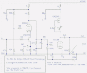
Talking of different designs, this one caught my eye - what do you think (see attachment)? Based on an old RCA circuit with a very low stage count - anyone tried this? If would be for direct MC use. Seems a little easier as a first project than the Allen Wright as there are less tubes..
I built a buck circuit to get a proper 220V to it, which lowered the HT from 317V to 256V as designed and I must say it does sound remarkably good, so I'll be intrigued to listen to a better one!
My system currently is RegaIII/RB300, Ortofon MC20 MkII super, Pickering PLZ pre-pre, Sheer Audio tube phono, Rotel RC-972, Usher R1.5, Usher X-718. Not very DIY and a bit multi-stage which is why I'm trying to rationalise and tubify it a bit! I use the Rotel for the remote volume, I need to figure how to connect one to my Peach FU50 when it arrives..
Talking of different designs, this one caught my eye - what do you think (see attachment)? Based on an old RCA circuit with a very low stage count - anyone tried this? If would be for direct MC use. Seems a little easier as a first project than the Allen Wright as there are less tubes..
Attachments
Last edited:
Talking of different designs, this one caught my eye - what do you think (see attachment)?
It looks like a problem to go with solution - why bother sticking JFET in there only to have to reduce its capacitance with cascode arrangement ? If you want pentodish characteristics and gain, use a pentode 😕
Anyway, if you take a look at your schematic you will notice there are three gain stages as well: cascode is arrangement of two stages (common source and common grid) and there's another common cathode stage afterwards.
If you want fewer tubes simply build a purely solid-state design 😀
I'm not sure of the advantage of a Jfet/tube cascode, but Allen Wright uses an identical topology so I think there must be one 😉. Perhaps a question for you then - are there any pentode input MC phono stages? and if not - why not?!
I see your point about the 3 gain stages, but the cascode ones are symbiotic and involve no coupling caps so I can see no better way - apart from your pentode idea 🙂
I have tried solid state designs, perhaps it's a headroom or linearity thing but none of them sound involving enough, and the latest one I tried (OK it was cheap) the Phono2 was incredibly boring to listen to. There is an A.n.t design one I listened too that sounded very good, but it was very small and very expensive, and had no glowy tubey things either 🙁
I'm not sure of the advantage of a Jfet/tube cascode, but Allen Wright uses an identical topology so I think there must be one 😉. Perhaps a question for you then - are there any pentode input MC phono stages? and if not - why not?!
The advantage is lower noise.
Google "pentode phono stage" (without ""), there are plenty of schematics floating around, I'm sure the authors have addressed nosie issue as well.
My system currently is RegaIII/RB300, Ortofon MC20 MkII super.
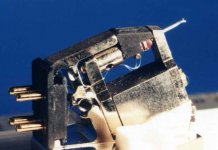
Slightly off topic, I know, but have you dared take the body off the Ortofon? I used to have one of those and really liked it - but it sounded even better with the body removed and a tight-fitting wedge of balsa wood pushed between the magnet and base plate. It's a terrible photograph, I know, but you should just about be able to see the white of the balsa underneath the white of the photographic flare.
Attachments
- Status
- Not open for further replies.
- Home
- Amplifiers
- Tubes / Valves
- Phono cathode follower challenge!!