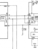
I've got a question about Philips CD-s based on TDA1541 DAC. Some of them have Pull-up resistor 3.9k (3329 on "typical" Philips PCB) connected to pin1 of TDA1541 (WS). Some - to pin2 (BCK). Which option is right? How does it works here?
PS: Sorry for my bad English.
PS: Sorry for my bad English.
Attachments
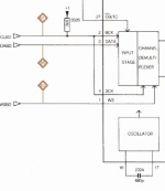
TDA1541 can receive input data in time multiplexed or simultaneous mode and this is determined by the connection of pin 27 to -5, +5 or GND. Consequently, pins 1 to 4 change their assignments and the pull-up resistors (they can also be 4K7) are applied.
TDA1541 can receive input data in time multiplexed or simultaneous mode and this is determined by the connection of pin 27 to -5, +5 or GND. Consequently, pins 1 to 4 change their assignments and the pull-up resistors (they can also be 4K7) are applied.
First pic. Its Grundig CD-9000. Second - Philips CD650. Both of them have +5v on 27 pin. But pull-up resistors are not the same. I am confused...
It doesn't actually require a resistor, certainly not a specific value - read the datasheet. And for example, Naim TDA1541A-based players just apply full+5v supply to pin 27 to set I2S input.
- Status
- Not open for further replies.