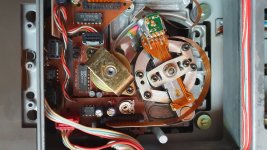
I have a Marantz CD-94 CD-player with CDM-1 optical unit. When I checked the laser current setting according to the service manual wich should be 575 mV +/-75 mV to GND at the test point (Q315 emitter), I found that it is only 260 mV.
The eye pattern is also blurred and there are occassional dropouts. The amplitude is about 1 Vpp.
Is it safe to readjust the laser current? I haven't touched it as long as this player is with me.
The eye pattern is also blurred and there are occassional dropouts. The amplitude is about 1 Vpp.
Is it safe to readjust the laser current? I haven't touched it as long as this player is with me.
I've not worked on the Marantz player but the standard Philips method of setting laser power looks at the total photodiode current and uses that value as an indirect measure of laser intensity. As such it depends totally on the reflectivity of the disc. Tbh I've never held much score by this method and always used the actual pk/pk value of RF as a guide which from memory was typically around 1 to 1.2v pk/pk so you are probably OK at 1 v pk/pk.
Measure with a normal representative sample of a commercial pressed disc. Most discs are fairly similar for reflectivity but occasionally a low or high example emerges. Disregard these and pick an average one. Use a divider probe and make sure the probe compensation trimmer is correctly adjusted as that makes a massive difference to displayed amplitudes of the RF on the scope.
You must use the correct grounds for the scope probe to see the clearest RF, it makes a big difference. Dropouts of RF (noticeable at a slow time base speed) are usually caused by issues with the disc itself. See if they occur at the same time point on the disc.

I have the same player. MK2.
I had to resolder every single joint! If you havent done that already especially on the servo board then it has to be be done!
Is the pot itself ok? Dirty? Make sure the cap you used in the servo is very low ESR.
Clean lens it affect the MV. Adjust the screw under the motor it affect MV. Both of these affect eye pattern!
It took me months to get mine working but still has issues LOL
Your setting is very low. It should not drift that much. I measured mine before and after recap maybe 50-100MV difference. Yours is very low. Maybe accidentially hit?
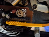
I just use a good factory CD, solder wires across that resistor on the PCB on top of CD player and slowly adjust the pot (closes to ribbon cable) and measure and adjust and measure again. I do it in steps as its difficult to adjust and meaure at the same time. I set mine to around 500MV
I just use a good factory CD, solder wires across that resistor on the PCB on top of CD player and slowly adjust the pot (closes to ribbon cable) and measure and adjust and measure again. I do it in steps as its difficult to adjust and meaure at the same time. I set mine to around 500MV
Would it be better to measure the laser current directly, in the wire connecting to the laser diode? The datasheet says it is typically 65 mA, and the optical power is 3 mW. Or measuring the laser power wit a suitable optical power meter?
As I understand the optical power is monitored by an internal photodiode that controls the power servo loop. So it should work without a CD in service position.
As I understand the optical power is monitored by an internal photodiode that controls the power servo loop. So it should work without a CD in service position.
Attachments
I wouldn't try and break the circuit and use an ammeter, any spikes would spell death to the laser.
Power meters are not always easy to use, I've been there... we had to have them to get Sony service accreditation but they were never used. It doesn't matter what a power meter says or what the current actually is if the RF level is incorrect. The RF imo has to be the final decider.
65ma is about right for the old Sharp LT022C laser diode but there is no way you can set laser power by setting a fixed current because once lasing starts a very small increase in current leads to a very large increase in optical output, in fact... 😉
The laser current is totally independent of the CD. This is such a fundamental point it needs clarifying.
The laser diode, the LT022C has an inbuilt photo diode on the same die as the laser that monitors the OPTICAL output of the laser. The APC (automatic power control) loop keeps the OPTICAL output from the laser constant. The CD has no bearing on this.
The confusion comes from setting the power by monitoring the "current" from the photo diode array. You are setting the laser power BY REFERENCE to the reflected signal. Remove the CD and the laser power is still set at that same level.
If the laser current had been determined by the reflectivity of the disc, which it isn't, then any CD would produce a similar photodiode current as the power would compensate automatically. I have often though this would be an ideal situation but in practice is fraught with difficulty. The laser would have to operate within safe limits, no reflected light (no CD) and the power would try and increase destroying the laser. Remember laser diodes can be destroyed in a matter of pico seconds with current spikes and that is one reason the power is monitored as it is on the die itself.
Other manufacturers used to recommend a "laser power meter" ... a calibrated photo diode and meter basically to monitor the "light" emitted from the objective lens.
First Mooly knows far more than I ever will and second I am no engineer only what I read in forums or have experience with. Saying that my experience is:
Stop over engineering it, once set correctly works perfectly fine with no flaws. I'm actually trying to fix my CD104 (also CDM1) in another thread.
Just get a very good original pressed CD or two. Solder 2 wires on the PCB with the resistor you have to measure and connect to Multimeter. Press play and measure. No need for test mode or anything. See the reading. If service manual says 500MV then do it if its says 575MV then do that. The reading will vary for example.
track 1 playing: set at 500mv initally but rising and falling +- 50-75MV thats very normal
track 10 playing: 550MV +- 50-77MV that also very normal
Your second CD might give you different results as long as its not too different and plays fine then you know you got it! I only use one CD ever to set and everytime works fine with everything else.
Just make sure:
1, all joints on pcb on laser is soldered again.
2, all new very low ESR (Panasonic / OSCON) could be other but thats all I know.
3, check the turntable motor plate (DO NOT UNSCREW THE MIDDLE SCREW) see the little plastic bit how worn it is. There is a guide online, just type CDM 1 service. Follow guide depending on condition. I had to sand mine right down and put back. Do height adjustments to read properly again.
4, if you haven't already grease/oil everything!
5, clean the hell out of the lens itself.
6, now adjust the voltage
After that if your laser itself is good, it should work flawlessly. Even on skipped tracks. If you skip anyof the parts I mentioned you will in someway run into problems.
Thanks for the useful advices. So is it safe to adjust the volltage on the monitoring resistor from the current 260 mV to the target 575 mV, while also monitoring the eye pattern amplitude? Or just adjust the laser current until the eye pattern amplitude will be 1.2 Vpp? It is currently around 1 V and a bit noisy.
For your own curiosity why not set the voltage to this target value and see how that relates to RF level. I always used RF level and nothing else. If the signal is noisy then that is something else beside just a power setting. You absolutely must use the correct ground for the scope to view the RF cleanly.
I think the eye pattern has to do with the height of the turntable motor (spindle). I don't understand the whole 1.2Vpp part sorry. I'm not that technical.
If its noisy or bad its probably the height of the motor. Check it first and fix that and fit it back just to allow you to continue your testing. You will know if its a good height as the tracks will work at begining and end perfectly and not skip.
You can set the laser strength first as it doesnt need tweaking afterwards, then do the height adjustment to get it perfect (after you took it out and checked it first). I checked the eye pettern on my cope and there was very little change when it was higher or lower but there is a "sweet" spot. You will know it when you keep changing tracks. Note also the speed of the track changes etc its a good indication of the sweet spot.
Just reemebr all my steps are important to get a stable laser if its a good laser already. Caps are very important, if its not low ESR change it. Dry joints etc....
The RF or Eye Pattern level is directly related to the optical output of the laser and the nominal 1.2 volt peak to peak level of the recovered signal from the photodiode array. At this point it is an analogue signal. The stages that process the RF are designed to operate with this nominal 1.2 volts pk/pk input signal and the first stage is a 'data slicer' (like a comparator) that converts the analogue transitions into a data stream of 1's and 0's. That data slicer works on this nominal 1.2 volts pk/pk analogue input level.
Altering the turntable height alters the 'fixed' bias voltage needed to bring the lens into focus on the disc. If you raise the height then the bias voltage needed is less and vice versa. This 'fixed' bias voltage is still modulated as necessary to track the moving disc. The height should be correct to ensure the lens is operating in the correct mechanical region of the lens suspension assembly.
Altering the turntable height alters the 'fixed' bias voltage needed to bring the lens into focus on the disc. If you raise the height then the bias voltage needed is less and vice versa. This 'fixed' bias voltage is still modulated as necessary to track the moving disc. The height should be correct to ensure the lens is operating in the correct mechanical region of the lens suspension assembly.
I adjusted the turntable height with the motor supporting Torxx screw so that the FOC- signal is around 0 Volts checked on an oscilloscope. The laser current adjustment range is up to 450 mV on the test point. It is at the upper limit of the adjustment varable resistor. Now I get 1.2 Vpp, but it is still noisy. I wiil check if it plays without dropouts now.
How did you get the 0 Volts? I read about that but no idea on how to do it.
Theres something wrong. It should be at the upper limit. Mine is just gone past half way with plently more room. Can you send a photo?
Did you check the bad joints and used low ESR capacitors in the laser pcb?
Theres something wrong. It should be at the upper limit. Mine is just gone past half way with plently more room. Can you send a photo?
Did you check the bad joints and used low ESR capacitors in the laser pcb?
I measured the voltage on the Servo PCB J203/6, and turned the Torx screw until it is closest to 0 V at the beginning and at the end of most discs.
Also I performed the Focus BW (or Focus Gain) adjustment as described in the SM, watching the Lissajous pattern and all that. It does not make much difference, TBH. Photo attached.
Also I performed the Focus BW (or Focus Gain) adjustment as described in the SM, watching the Lissajous pattern and all that. It does not make much difference, TBH. Photo attached.
Attachments
I will have to look for this j203/6 not sure where it is.
Look at my cd104 the pot has plently to room still. This measure 500MV on a good CD. Something is definitely wrong with yours. Is the pot itself ok or dirty? Did you solder the PCB board? Your capacitors look good. Did you completetly recap the whole cd player and resolder bad joints?
If you turned it the whole way and only get 450MV something definitely not good. I've read cleaning the lens can seriously affect the MV ouput. Check that aswell.
Attachments
Did you completetly recap the whole cd player and resolder bad joints?
No, I did only the cdm pcb. The rest is too much effort, and I am not sure it would influence the laser current. Maybe I'll check the Servo Module PCB (that is not the same as the much bigger Servo PCB, and has mostly SMD components).
No, I did only the cdm pcb. The rest is too much effort, and I am not sure it would influence the laser current. Maybe I'll check the Servo Module PCB (that is not the same as the much bigger Servo PCB, and has mostly SMD components).
You need to check all supplies coming into that PCB. By not doing the PSU sections and servo boards you have potentially created a problem for yourself. Because I am not as techinical I always start with PSU board, new capacitors, resolder. Then I know for certain its not that. Otherwise I will never know and give up.
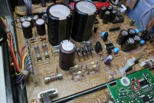
Have you chekced the main transistor that gets hot on the laser pcb? Or the resistor (red one). It seems somehow you have low voltage.
Definitely some issue and not so much related to laser alignment.
Have you chekced the main transistor that gets hot on the laser pcb? Or the resistor (red one). It seems somehow you have low voltage.
Definitely some issue and not so much related to laser alignment.
Thanks, I will check those. I left the player running overnight in repeat/shuffle and it did not fail.
I replaced most electrolytic capacitors on the power PCB and on the Servo PCB (they were good). Nothing changed.
The SM says on page 10 Fine adjustment of laser current that 575 mV should be measured on the resistor 3308 on the Servo PCB. The issue is that there is no such resistor on the Servo PCB or anywhere else. But! The Philips CD304 Mk II has it. Compared the circuit diagrams, the test point on the CD-94 must be TP35 that is R309 connected to emitter of Q315. The circuits are more or less identical. This part of the servo is somehow related to radial error correcion. It is not clear for me, what has the laser current to do with radial error.
The SM says on page 10 Fine adjustment of laser current that 575 mV should be measured on the resistor 3308 on the Servo PCB. The issue is that there is no such resistor on the Servo PCB or anywhere else. But! The Philips CD304 Mk II has it. Compared the circuit diagrams, the test point on the CD-94 must be TP35 that is R309 connected to emitter of Q315. The circuits are more or less identical. This part of the servo is somehow related to radial error correcion. It is not clear for me, what has the laser current to do with radial error.
I got the image from online. Look at the green PCB, I found mine mine on the green PCB by the top white platic hole. Its a very small resistor. I measured that and set my voltage for laser
literally in the red circle
literally in the red circle
Attachments

Last edited:
- Home
- Source & Line
- Digital Source
- Philips CDM-1 laser current