I was trying to some information on the importance of phase tracking in crossovers. The best information I could find suggests maintaining a minimum 45 degrees one octave above and one octave below the crossover frequency. Of course if you are using low order crossovers then you might want to increase this to two octaves above and below.
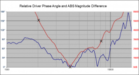
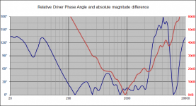
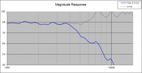
Here is an simulation from a speaker I am activating with 7th order butterworth filters @4100 Hz for mid and tweeter in a DSP. The picture shows the relative phase difference and the absolute magnitude difference between the mid and the tweeter. One octave above above and below are marked with X.
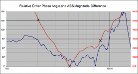
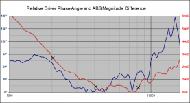
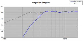
The second picture is the same as the first but with a 0.01ms delay between the drivers. It forces the hump down a bit but now the phase difference is 20 degrees @4100 Hz.
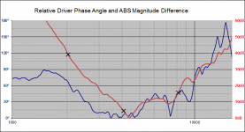
The third picture is the original analogue crossover in the speaker.
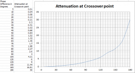
The fourth picture just a graph of phase difference versus attention - imagine two perfect drivers subjected to a phase difference of 90 degrees resulting in a 3 dB attenuation.
The question is: Which one should sound better? Crossover 1 or 2?
Here is an simulation from a speaker I am activating with 7th order butterworth filters @4100 Hz for mid and tweeter in a DSP. The picture shows the relative phase difference and the absolute magnitude difference between the mid and the tweeter. One octave above above and below are marked with X.
The second picture is the same as the first but with a 0.01ms delay between the drivers. It forces the hump down a bit but now the phase difference is 20 degrees @4100 Hz.
The third picture is the original analogue crossover in the speaker.
The fourth picture just a graph of phase difference versus attention - imagine two perfect drivers subjected to a phase difference of 90 degrees resulting in a 3 dB attenuation.
The question is: Which one should sound better? Crossover 1 or 2?
Attachments

Last edited:
There's just something about DSP that makes people want to kill every fly with a massive hammer. 🙂 And this from a guy who loves his miniDSP.
Forget phase matching, why are you using such high slopes? Even with the DSP, 2nd to 4th order is usually ideal. Once you dial that down, phase matching will be easier and more sane.
Then we can talk about pretty slopes. 🙂 But to give you an idea of what a good target might be see
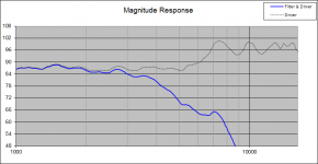
the phase matching from my blog entry on the LM-1 crossover:

See how the phase approach each other gently at 400Hz, dance tightly through the crossover, and then gently separate round 4kHz?
You should be able to get something like that by sticking to lower order filters.
Best,
Erik
Forget phase matching, why are you using such high slopes? Even with the DSP, 2nd to 4th order is usually ideal. Once you dial that down, phase matching will be easier and more sane.
Then we can talk about pretty slopes. 🙂 But to give you an idea of what a good target might be see
the phase matching from my blog entry on the LM-1 crossover:
See how the phase approach each other gently at 400Hz, dance tightly through the crossover, and then gently separate round 4kHz?
You should be able to get something like that by sticking to lower order filters.
Best,
Erik
Last edited:
You have chosen to set boundaries based on frequency away from the crossover point. Maybe you could use the relative pressure difference to set this boundary as this is what matters.
Phase differences are going to alter the response on the listening axis and this is going to set your baseline equalisation, yet the power into the room isn't necessarily going to follow that trend so it may make a noticeable difference.
Phase differences are going to alter the response on the listening axis and this is going to set your baseline equalisation, yet the power into the room isn't necessarily going to follow that trend so it may make a noticeable difference.
+1 AllenB!
Look at my chart and see the -20 dB locations? That's what he's talking about. I think. 🙂
Look at my chart and see the -20 dB locations? That's what he's talking about. I think. 🙂
The cone (titanium) breakup of my mids is quite nasty. From 5 Khz to 7.2 KHz the response rises 13 decibels. See the first picture.why are you using such high slopes?
Yes I see that effect too in the second picture I have a 5th order butterworth and the phase behaves better. Compare this to the first picture in my first post(a BW7).[/QUOTE]Even with the DSP, 2nd to 4th order is usually ideal. Once you dial that down, phase matching will be easier and more sane.
Do you have a link to your xsim file? I will make and post a diagram of relative phase difference and the absolute magnitude difference.
Cheers, BTW nice blog - good reading for my weekend
Attachments

Last edited:
The cone (titanium) breakup of my mids is quite nasty. From 5 Khz to 7.2 KHz the response rises 13 decibels. See the first picture.
Then may I suggest you consider lowering the crossover frequency if at all possible? If you've got large bell-mode resonances coming in within about 1/4 octave of the XO -that's not good. OK, you can keep it as-is & try the brute-force approach of extremely steep crossovers or a large notch on the main let-go mode. The former is likely the least of the evils but even B5 is unlikely to be sufficient & LR6 probably the minimum. Trouble is, even if you notch out a major resonance, its effects on HD are still likely to be present, so the further you can realistically keep away from that region (and the lower in level you can realistically shunt it) the better. Lowering the XO frequency a bit, assuming that to be possible, may allow you to use slightly less extreme slopes which should, as Eric and Allen note, make phase matching easier. High order filters are usually harder to optimise than slightly lower order filters, with 4th order usually being the easiest to get working well (which is why it's popular). Of course, I'm not exactly in a position to cast stones since I have a fondness for (passive) 5th order filters, probably because they're not very common.
I would add parametric EQ to that first, then add the low pass filter. Even without, a 7th order seems too much. Almost all mid-woofers do something like that.
Almost all mid-woofers do something like that
...and are frequently misused as a result. It's part of the continuing obsession over nominally pistonic behaviour. The analogy of pistons to MC drive units is somewhat dodgy, but taking it purely at face value, if you want to maximise the nominal benefits you need to be crossing sufficiently far below the main let-go mode, and at a sufficiently high order to shunt it to a low enough level that the HD products (which go down as well as up in frequency) are inaudible. Arguably you can go overboard on this, so you need to ensure that the cure doesn't cause more problems than it solves. Good enough is good enough. In this case, I'd be inclined to lower the XO frequency somewhat as a first move, assuming the tweeter can handle it.
Scotts orderof operations is correct. Try low order fiters and lower f first, the compensate if needed.
I will look into this. My speakers are Visaton Vox 253 MTI with M-T-M and side bass. The mids are crossed at 135 Hz and 4100 Hz. I really want to stay with those crossover points as I want as much frequency range as possible to come from the mids. As I have DSP nanoDIGI I can instantly flip between 4 presets 🙂Then may I suggest you consider lowering the crossover frequency if at all possible?
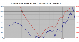
@eriksquires - The first picture here is the phase difference and absolute magnitude difference of your LM-1. The second one is the Butterworth 7 from my first post. Your 20 dB points are possibly not quite as good as you thought.
Attachments

When one driver is -20dB compared with the other it doesn't have much effect. It can still be heard and the errors are still of concern but it's on the right track. Try 24 or 32 if you can, but don't allow chasing the extremes to compromise the middle.
Actually the errors on my BW7 are not as bad as I thought. I made an error in the Q value.When one driver is -20dB compared with the other it doesn't have much effect. It can still be heard and the errors are still of concern but it's on the right track. Try 24 or 32 if you can, but don't allow chasing the extremes to compromise the middle.
Attached corrected BW7, BW5, BW3
Attachments
Getting more specific, on the first plot in your last post at 7kHz there is a dip toward less pressure difference between the drivers. Is this due to a peak in the midrange driver there? When you rely on the phase difference to predict for you the total response it assumes the two drivers are summing cleanly, but they won't be.
In short, the mid is out of its depth there. When the cone breakup region is approached the mid will behave differently to the tweeter and the summation might only be as predicted at the same angle as you took the measurements. Reflected sound may be all over the place and out of balance, not to mention also by driver spacing at the much higher than crossover frequencies.
Broadly speaking you should start by aiming for symmetrical ideal curves on each driver, ensuring that the breakup peak is also down a reasonable amount.
Last edited:
Thanks for the tips.Getting more specific, on the first plot in your last post at 7kHz there is a dip toward less pressure difference between the drivers. Is this due to a peak in the midrange driver there?
Yes the dip is there.
Attachments
It seems OK, but smoothing that peak could be worth a little attention. However, how to do so won't be clear from your single axial measurements. Not to worry you could guess by say, setting this as an upper limit deciding to have it down by a certain level and setting a moderate slope enough below this. Additionally you could notch the peak, but remember that it is superficially an axial peak so don't be heavy handed.
Consider also the size of the midrange cone with regard to it providing as wide directivity as the tweeter at the crossover. Then consider the capabilities of the tweeter, and whether the drivers sound happy within these bands. At some point you'll arrive at an optimum crossover point (if they support one).
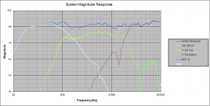
The last plot on your last post shows you have two mids. How are they physically arranged and how are they baffled? Their slopes seem inappropriate, broadly speaking they ought to be each 12dB down where the outer drivers are down 6dB.
Consider also the size of the midrange cone with regard to it providing as wide directivity as the tweeter at the crossover. Then consider the capabilities of the tweeter, and whether the drivers sound happy within these bands. At some point you'll arrive at an optimum crossover point (if they support one).
The last plot on your last post shows you have two mids. How are they physically arranged and how are they baffled? Their slopes seem inappropriate, broadly speaking they ought to be each 12dB down where the outer drivers are down 6dB.
My amplifier will be converted from 4 channel to 6 channel soon. So I might just make some directivity sonogrammes with ARTA over Christmas for the original crossover and a few variants of my new DSP nanoDIGI crossovers.Consider also the size of the midrange cone with regard to it providing as wide directivity as the tweeter at the crossover. Then consider the capabilities of the tweeter, and whether the drivers sound happy within these bands. At some point you'll arrive at an optimum crossover point (if they support one).
Here is a picture. The baffle is 160 mm with two 45 degree chamfers making the box 235 mm wide.The last plot on your last post shows you have two mids. How are they physically arranged and how are they baffled? Their slopes seem inappropriate, broadly speaking they ought to be each 12dB down where the outer drivers are down 6dB.
The attached directivity diagram from manufacturer (Visaton Ti 100) suggests these peaks are of an axial nature - the titanium cone has a phase plug, perhaps this helps to keep the nasties axial. The tweeter is a magnetostat MagnetostatAdditionally you could notch the peak, but remember that it is superficially an axial peak so don't be heavy handed.
Attachments
When different parts of the cone begin moving independently from each other, sound can be distributed differently and the directivity and response can appear chaotic. Normally it is better to avoid this altogether.
Blanket statements like taking the peak down 30dB might make a good rule of thumb, there are some situations where the driver is run close to the peaks (such as when the cone size is used to narrow the beam to match a narrow tweeter). Titanium drivers are notorious for their breakup characteristic.
Blanket statements like taking the peak down 30dB might make a good rule of thumb, there are some situations where the driver is run close to the peaks (such as when the cone size is used to narrow the beam to match a narrow tweeter). Titanium drivers are notorious for their breakup characteristic.

- Status
- Not open for further replies.
- Home
- Loudspeakers
- Multi-Way
- Phase tracking in crossovers