For those who have full comp 400II or 700II's and want to bring it into the 21st century (at least regarding a triple EF), I offer a modification that I have been experimenting with.
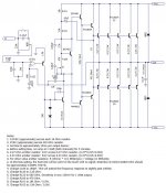
It is a simple circuit revision that reconfigures the amp for more bandwidth and less distortion. The circuit revision is based on the PL-36 driver board. I have not attempted to revise the earlier all discrete driver board(s). The modification addresses the way the pre-drivers and drivers are configured. A feedback cap is also changed to increase the bandwidth slightly that the full comp output section can now easily handle.
Input sensitivity has also been reduced to a more manageable level, since it was too sensitive IMO. It is now 150mV input for 1 Watt out into 8 Ohms.
On this particular driver board, I do not have the original Phase Linear VAS transistors with the steel heat sink. To keep my substitute VAS (2N3440) running cool(er) with an aluminum heat sink, I elected to reduce the VAS current by re-configuring the VAS collector boot-strap circuit. I used the circuit values from the 700B driver board. These resistors are R101 and R103 on the PL-36 driver board. This part of the modification is not necessary to increase the bandwidth or reduce distortion, but as I said, it does allow the VAS to run cooler when you do not have the original steel heat sink.
The attached schematic does not have all of the circuit values, but it does contain all the revision values. It was drawn for brevity. Please have the original schematic on hand if you are not too familiar with the PL-36 driver board.
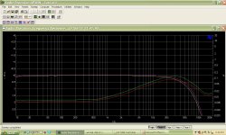
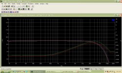
I'll post more pictures later and a few AP graphs of the performance.
It is a simple circuit revision that reconfigures the amp for more bandwidth and less distortion. The circuit revision is based on the PL-36 driver board. I have not attempted to revise the earlier all discrete driver board(s). The modification addresses the way the pre-drivers and drivers are configured. A feedback cap is also changed to increase the bandwidth slightly that the full comp output section can now easily handle.
Input sensitivity has also been reduced to a more manageable level, since it was too sensitive IMO. It is now 150mV input for 1 Watt out into 8 Ohms.
On this particular driver board, I do not have the original Phase Linear VAS transistors with the steel heat sink. To keep my substitute VAS (2N3440) running cool(er) with an aluminum heat sink, I elected to reduce the VAS current by re-configuring the VAS collector boot-strap circuit. I used the circuit values from the 700B driver board. These resistors are R101 and R103 on the PL-36 driver board. This part of the modification is not necessary to increase the bandwidth or reduce distortion, but as I said, it does allow the VAS to run cooler when you do not have the original steel heat sink.
The attached schematic does not have all of the circuit values, but it does contain all the revision values. It was drawn for brevity. Please have the original schematic on hand if you are not too familiar with the PL-36 driver board.
I'll post more pictures later and a few AP graphs of the performance.
Attachments
Last edited:
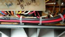
The second image shows the 330 Ohm resistor soldered between the two legs of the pre-driver transistors emitters.
The third image shows how I used two 18 Ohm resistors to emulate one 36 Ohm resistor. I wanted the mod to be clean, so this is what I came up with.
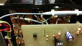
The first image is showing the heat sinks that I am using for the VAS/2N3440.
The third image shows how I used two 18 Ohm resistors to emulate one 36 Ohm resistor. I wanted the mod to be clean, so this is what I came up with.
The first image is showing the heat sinks that I am using for the VAS/2N3440.
Attachments
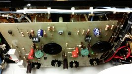
Some history of this (poor) amp... it is a 700B that had been raped and pillaged. Meters were mis-matched and do not work (still don't), no outputs or drivers, main caps were dented and screw threads were stripped, half of all the emitter resistors were burnt or missing, no rail fuse covers (main fuse cover intact), no driver board and some sockets damaged or not usable. However, the power transformer was in good shape as well as the chassis (in general).
I bought it from a fellow Phase Linear tinkerer who had hopes of restoring it, but he knew it would never get the attention it needed, so I acquired it for next to nothing. I bought it with the intention of using it for testing different circuit modifications, hence it is my 700 test mule.
I replaced the main filter caps, bridge rectifier and rewired the output section for full comp operation. Front level pots are on the face, but not connected (on purpose).
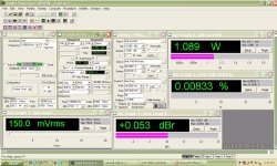
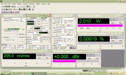
Below is 1 Watt into 8 Ohms
I bought it from a fellow Phase Linear tinkerer who had hopes of restoring it, but he knew it would never get the attention it needed, so I acquired it for next to nothing. I bought it with the intention of using it for testing different circuit modifications, hence it is my 700 test mule.
I replaced the main filter caps, bridge rectifier and rewired the output section for full comp operation. Front level pots are on the face, but not connected (on purpose).
Below is 1 Watt into 8 Ohms
Attachments
Last edited:
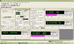
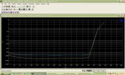
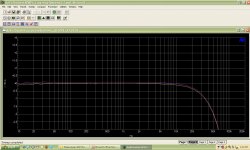
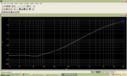
2 Watts into 8 Ohms and power output vs THD+N
Attachments

Last edited:
- Status
- Not open for further replies.