Phase inverter Gremlins in power amp help wanted
Hello all, I have been trying to find the source of this terrible combination of low level "buzz" and "hiss" that sounds very much like an oscillation problem. The amp is an old Philips EL6431, it has been rebuilt from a what was crusty rusty junker to something that would sound very good and knock the house down if it wasn't for the back ground noise "gremlins".
I will not get into much detail, I have an entire restoration thread about it on another forum with schematics that are no longer valid to what I have done to the poor thing at this current time.
I am looking for help on what to do next, and hopefully some one out there has seen this sort of noise before and found the source of their problem.
What have I not tried yet? I don't know, if I were to list what I have tried it would take too long so just throw me some ideas. 😀
Restoration thread: DIY Audio Projects Forum • A 120 watt Beast Philips EL6431 Tube Amp
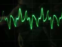
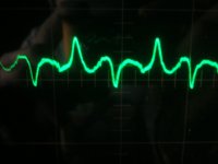
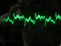
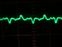
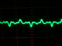
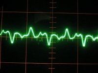
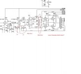
The pictures are as follows; The first two are taken from the output of the phase inverter, the third is taken from the output of the amp. The next two are from the output of the phase inverter again, after changing to williamson type circuit as a last attempt.
Any help is very much appreciated
Hello all, I have been trying to find the source of this terrible combination of low level "buzz" and "hiss" that sounds very much like an oscillation problem. The amp is an old Philips EL6431, it has been rebuilt from a what was crusty rusty junker to something that would sound very good and knock the house down if it wasn't for the back ground noise "gremlins".
I will not get into much detail, I have an entire restoration thread about it on another forum with schematics that are no longer valid to what I have done to the poor thing at this current time.
I am looking for help on what to do next, and hopefully some one out there has seen this sort of noise before and found the source of their problem.
What have I not tried yet? I don't know, if I were to list what I have tried it would take too long so just throw me some ideas. 😀
Restoration thread: DIY Audio Projects Forum • A 120 watt Beast Philips EL6431 Tube Amp
The pictures are as follows; The first two are taken from the output of the phase inverter, the third is taken from the output of the amp. The next two are from the output of the phase inverter again, after changing to williamson type circuit as a last attempt.
Any help is very much appreciated
Attachments
Last edited:
Not very helpful: no time scale, no amplitude scale.
Based on the little you've given, it looks like multiple problems. The overall sawtooth aspect looks like PS ripple from a ground loop somewhere. There also seems to be a superimposed oscillation coming from somewhere. Williamson type amps were notorious for this, due to the heavy gNFB used. The Williamson got by with this due to its Partridge OPTs with a very wide BW for phase margin that more conventional OPTs can't provide.
It would also be helpful to see the output from earlier gain stages.
If you want more definitive answers, more info please.
You are right about power supply ripple and ground loops being a source, and since you asked for some more info I will try my best to provide it to the best of my knowledge, beginning with more lengthy explanation that probably means nothing, but what the heck.
For a start the original circuit is NOT Williamson, the phase inverter is what I believe to be a LTP, correct me if I'm wrong.
The original service info and schematics for this amp can be found here: Philips EL6431
I changed the circuit to Williamson type after trying the guts of an W-1 Heathkit and stealing the driver and phase inverter then fed the output stage of the philips amp, and roughed a 20K with 100pF cap for feedback.
The result sounded excellent considering and the noise was gone!
Changing the circuit over seems to have reduced the noise some but it is still there, witch pushes me towards ground loops more so than supply noise since everything is pretty much regulated and pretty darn quiet and the scope doesn't really tell me much since it doesn't really work very accurately and is running from a variac to keep the horizontal deflection supply from blowing up.
The scope does not pick up anything before the phase inverter, but as implied I don't know how accurate or sensitive it really is. Tracing the signal with a probe and a head amp I found nothing audible either, but I will check again since that was before the circuit change. The reading was made on a vert. atten. of 1 AC and sweep of 10hz? The noise sounds like higher than 60hz, for like double that with a bit of white noise mixed in as well, or a noisy power tranny or rectifier, or shorted input to ground but out of the range of being considered "hum".
The schematics are not exact to what is current, and yes the output stage runs over 800V on the plates, it runs nice and warm.... I did change the bias from -33V to -35V and has an improperly implemented shut off if bias drops below -30 volts.
Much of the stuff I have done to this amp is using circuits that others have designed and I have just "tweaked" them using what I know about electronics and tube based circuits, this is why I am looking for advice from others, I'm doing something wrong but don't know what, I suppose not doing enough reading would be part of it...🙄
I think I'm gonna borrow a better scope from some one....
Thanks for the help
Attachments
I saw similar to the 2nd pic in a friend’s preamp section of his old Ampeg Accordion/Guitar amp. Had already replaced the filters. I messed with the heater circuit and even tried dc in the preamp at one point and still had the hum/buzz. It was 60hz from peaks to peaks. I called it “Batman” since it looks like the logo. For me it was bad tubes. They were new Sovtek 6SL7s. I put in NOS American ones and the problem went away. I was very surprised.
Your issue could be much different of course, but sound/look the same.
Your issue could be much different of course, but sound/look the same.
Attachments
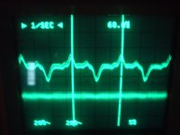
As for not being able to detect the noise from earlier stages, this is what I would expect for power supply noise. It increases as you move towards the finals. If that 'scope is calibrated at all accurately, it also looks like there's some low frequency instability of ~16Hz. That's pretty much in line with the low end of the OPT. The only question that remains, does it go away if the feedback is disconnected? Low frequency instability can occur while running open loop, and the culprit if it's still there is often inadequate bypassing and load isolation. If it's there only with the NFB connected, then it's a lack of phase margin on the low end. That would be inadequate staggering of RC time constants in the coupling between stages, and there seems to be a lot of those.
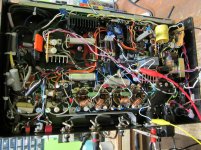
That schemo you posted is just a mess. I don't see how the hell that thing works at all. 825V for an EL34? That's quite a spec bust right there, as it's specced for about 400V. 800+ volts is what I'd expect for a power RF type like the 814, not an audio type like the EL34. The NFB seems to be shorted out by the cathode bypass capacitor of the second half of the 12AX7 (after the tone stack). You have coils shorting out the grids of the finals, unless they're very big. The plate stopper inductors don't have de-Qing resistors.
It looks like you have a collector coupled multivibrator that's doing nothing (cool looking blinkenlichten for the panel?) that's going to make a helluvalot of noise. I'd get rid of that.
EL34 is specified for 800V at plate and 400V at screen , you can see this config in many old amps like e.g. Dynacord. 825V is no problem for NOS (my experience), might be at the limit for todays production.
Regarding the issue: The best might be to restart this build from scratch again. First PS and grounding, then Powerstage, PI and so on, verifying after each step the results. It seems to be painful but might be faster at the end.
Regarding the issue: The best might be to restart this build from scratch again. First PS and grounding, then Powerstage, PI and so on, verifying after each step the results. It seems to be painful but might be faster at the end.
I fully agree with ES345.
I build several of these beast amplifiers, with no problems.
When I look on the photo of the bottum part of the amplifier, than the possibility is very high you made several grounding errors.
Succes and regatds.
M
I build several of these beast amplifiers, with no problems.
When I look on the photo of the bottum part of the amplifier, than the possibility is very high you made several grounding errors.
Succes and regatds.
M
Thanks for the help guys, I will try a few suggested changes and see what happens, I will remove the feedback and see what that does and try a few other tubes as well.
The most dissapointing part of this rebuild for me is that the sound was exactly what I wanted for use as a PA and bass amp and it seemed quite stable, I had my friend play through the amp with his guitar and he loved it! Amazing overdrive, and it sounds very clean with a bass when the overdrive is off.
I just can't stand listening to the background buzz, and that scope signal looks similar to what I get jjman, I have a friend who encountered the same problem with an amp he was working on.
As for redoing the circuit properly I havn't a clue, I just don't know enough theory build an amp from scratch, all I can do is modify circuits based of my self taught knowledge.
If it means anything I rewound the power tranny and and that fixed a number of problems the amp originally had, In theory I don't even know how it ever worked in the first place, as the insulation pretty much crumbled apart. This did not get rid of the gremlin though.
So my next question is how should I rebuild it? Do I keep the old circuit? Do I look for a new one and change it to fit the amp? This sounds like a new thread entirely.
And Miles the blinking LED is for the panel, it flashes until the HV relay activates, I thought it was clever at the time, just one of the few things that actually works the way I wanted it to.
....double check schematic errors ? esp in power amp sec feedback arm 68pF shunted by 100uF ain't going to do much. This is a serious error. Apols for IE havoc.
richy
richy
Attachments
Last edited:
I no longer use that circuit now, I have a williamson type phase inverter and driver, actually here I will list the values and what has been changed...
Phase inverter: 12BH7 with 51K plate resistors 380V regulated using IRF830, CCS used as shown on the diagram, grid caps 0.1uF with 150K to ground.
Driver for phase inverter: 5751 with 27K plate and cathod resistor to ground, grid direct coupled(bypassed tone control stage) to to plate of input stage with 82K plate resistor and RC to ground using 100pF and 15K. Cathode resistor is 1.2K with 56uF feedback taken from here with 22K and 68pF cap(same as the typical williamson type arrangement)
Input grid cap is 0.18uF with 220K to ground.
I have seen similar scope traces when there is magnetic coupling between output transformer and power transformer, have you measured the output with no tubes at all?
(Just be carefull the B+ on those capacitors doesnt get too high when unloaded!)
(Just be carefull the B+ on those capacitors doesnt get too high when unloaded!)
rich read the post I made previously about the schematic changes, the diagram I posted is just for reference, it is no longer current. Also the grid bias inductor is an original part, disconnecting it did nothing, but I will be leaving it out when I rebuild the amp again, unless it has a better purpose other than just being there, I remember the manual mentioned something about it.
What should I see with the output tubes disconnected?
I could bring it up on the variac, my supply caps add up to 1000V so if it doesn't go over 950 or so I suspect it would be fine.
Another thing I should mention, I tried a new output at one point, a Hammond 1650T was the test subject, no change, so that confirmed the output was not the culprit early on.
Here is a video of the setup that I had at one point before deciding to change the circuit to williamson type, be very afraid!
Philips EL6431 PA driven with Williamson Phase Inverter - YouTube
Philips EL6431 PA driven with Williamson Phase Inverter - YouTube
Nothing at all, coming out of the OPT secondary.What should I see with the output tubes disconnected?
Given your complex powering arrangements, it would be a good idea to sketch a grounding schematic that shows how all distributed stars are connected. Identify major current carrying injection circuit points (filter cap terminals, output stage cathode, rectifier terminals, etc.) and links between stars. You should be able to identify all high current loops, and how they don't have common paths apart from filter caps.
The risk in rectifying everything including heaters is that there is a lot of diode commutation noise that links to all powering sections via the transformer windings.
The risk in rectifying everything including heaters is that there is a lot of diode commutation noise that links to all powering sections via the transformer windings.
- Status
- Not open for further replies.
- Home
- Amplifiers
- Tubes / Valves
- Phase inverter Gremlins in Philips EL6431 amp