I am quite new to electronics and have been doing some research to build a personal monitor system. I have looked at the CMoy headphone amp and adapting it to have 2 inputs with separate volume controls.
I have recently found this schematic of an active mixer which looks like it might suit my needs more (Bottom left schematic): http://www.all-electric.com/schematic/simp_mix.gif
For the personal monitor system I want 2 input (one for a Mic and one for guitar), each with a thru so they can go to the desk. I then want one headphone out that I can plug my IEM's into and a volume control for each input.
My questions are:
1. which circuit would be better for my system (CMoy or the active mixer in the link)
2. I Understand what a capacitor does but unsure why they are used in the active mixer). Can someone please explain thin to me?
3. After some research, I have found the LF347N op amp. I understand this has 4 op amps in side the one IC. Is this correct and would this be suitable for either circuits.
I hope this all makes sense,
Thanks in advance,
Joe
1. You'll need both, if making an active mixer. Whether CMoy or not, a mixer, with its own feedback loop, pushing a headphone amp, with its own feedback loop.
2. Protects against DC offset, and creates a high-pass filter (the latter is by necessity, not something wanted, so the cap value should be raised if the input resistor values are lowered). The average of the signal in will tend to make its way towards 0VDC between the input pin and virtual ground. They are needed for any external input that is not from a transformer, and may be a good idea on line outputs, too.
Are the guitar and mic signals already going through an amp to make them line-level signals?
I am quite new to electronics and have been doing some research to build a personal monitor system. I have looked at the CMoy headphone amp and adapting it to have 2 inputs with separate volume controls.
I have recently found this schematic of an active mixer which looks like it might suit my needs more (Bottom left schematic): http://www.all-electric.com/schematic/simp_mix.gif
For the personal monitor system I want 2 input (one for a Mic and one for guitar), each with a thru so they can go to the desk. I then want one headphone out that I can plug my IEM's into and a volume control for each input.
My questions are:
1. which circuit would be better for my system (CMoy or the active mixer in the link)
2. I Understand what a capacitor does but unsure why they are used in the active mixer). Can someone please explain thin to me?
3. After some research, I have found the LF347N op amp. I understand this has 4 op amps in side the one IC. Is this correct and would this be suitable for either circuits.
I hope this all makes sense,
Thanks in advance,
Joe
Joe, I don't know if you've checked back on this same post on the diyaudioprojects.com site, but I left a reply to it including a suggested circuit. I go by the same user name there too.
Here is a link to it for quickness:http://diyaudioprojects.com/Forum/viewtopic.php?f=10&t=5128
Last edited:
Are the guitar and mic signals already going through an amp to make them line-level signals?
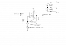
If not, see attached, a variable gain preamp to allow for different signal and bring them up to line level.
Attachments
Thank you both for your help. I have put together a circuit using the mixer, CMoy and preamp circuit gasboss775 suggested.
I have added a switch to allow me to switch between the input resistors allowing me to either have instrument or mic level. I will be using XLR/Jack combo sockets as inputs so that I could have 2 mics or 2 instruments if i decided to. I may even add a switch bypassing the preamp if i wanted to send a monitor mix from the engineer.
Does this look alright?
Thank you again for your help,
Joe.
I have added a switch to allow me to switch between the input resistors allowing me to either have instrument or mic level. I will be using XLR/Jack combo sockets as inputs so that I could have 2 mics or 2 instruments if i decided to. I may even add a switch bypassing the preamp if i wanted to send a monitor mix from the engineer.
An externally hosted image should be here but it was not working when we last tested it.
Does this look alright?
Thank you again for your help,
Joe.
I have just realised that R1b is a pot for gain. This is an altered version:
An externally hosted image should be here but it was not working when we last tested it.
Joe, Somehow I am unable to view your images, I don't know if this is to do with my android tablet, or if others are having the same problem. Did you upload the images to this site or is it a link to an image hosting site like image shack?
Probably best to upload here if you haven't.
Gordon.
Probably best to upload here if you haven't.
Gordon.
Hotlinking isn't working from the host. Right-click and open in a new tab or window, and it will show up.
bloodfromastone, thanks that worked!
Joe, the schematic is largely fine, only error that I can see is that the negative side of C8 is connected to earth as well as to the headphone amp. Also you forgot to connect the bottom end of the upper mixer pot to earth / ground.
Joe, the schematic is largely fine, only error that I can see is that the negative side of C8 is connected to earth as well as to the headphone amp. Also you forgot to connect the bottom end of the upper mixer pot to earth / ground.
A couple of comments:
1. On the pre-amps, the 1K resistors at the grounded end of the feedback chain are shown as 10K in the suggested schematic.
2. As noted above, the bottom of the volume control at the output of the top preamp needs to be grounded.
3. The two op amps in the mixer have their inputs inverted. The positive inputs need to be grounded, and the negative inputs receive the signal and the feedback. The first op amp causes a signal inversion which can't be avoided, and the second op amp is only there to restore the original phase relationship.
4. Also as noted above the output of C8 is grounded, which means one of your outputs is not going to work.
regards,
Mike
Last edited:
Perhaps the 1K was deliberate, it makes the minimum gain 10 ( 20dB ), still I think the original option of min 2 ( 6dB ) is more versatile.
I never noticed the mistake on the mixer opamps, well spotted Mike!
Another thought that I had. If the input impedance switches were DPDT then they could switch between 2 gain settings, by switching between different feedback resistors.
I never noticed the mistake on the mixer opamps, well spotted Mike!
Another thought that I had. If the input impedance switches were DPDT then they could switch between 2 gain settings, by switching between different feedback resistors.
Thank you all again for your help.
Does this one look better?
View image: Personal Monitor System 3
Joe
Does this one look better?
View image: Personal Monitor System 3
Joe
Thank you all again for your help.
Does this one look better?
View image: Personal Monitor System 3
Joe
Joe, just a thought. Do you realize that the headphone amp can only drive Hi-Z 'phones ( 600R min )
If you need this to drive 32 ohms or less, let me know as the opamps in the h/phone amp are going to need a booster stage added.
Gordon.
Joe, just a thought. Do you realize that the headphone amp can only drive Hi-Z 'phones ( 600R min )
If you need this to drive 32 ohms or less, let me know as the opamps in the h/phone amp are going to need a booster stage added.
Gordon.
Hi Gordon,
Thank you for letting me know, I was hoping to use something similar to the Shure SE215's which are 20 ohms. Is a booster pretty easy to add?
Thanks,
Joe
Hi Gordon,
Thank you for letting me know, I was hoping to use something similar to the Shure SE215's which are 20 ohms. Is a booster pretty easy to add?
Thanks,
Joe
Yes it is easy, I'm going to be busy this afternoon but I will try to show you how later today, barring any emergencies!
Gordon. 🙂
Joe, I've come up with two possible headphone amps, utilizing the existing opamp.
1. This is known as a current dumping amplifier and is simpler than the proper class AB output stage. The opamp feeds the 'phones directly via the 100 ohm resistor. When the opamp output current reaches approx +/- 6mA, there will be +/- 600mV across the base emitter junctions of the output transistors, the NPN for the positive cycles and the PNP for the negative cycles, the transistors thereafter provide the additional current necessary to power low impedance headphones.
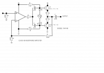
2. This is the proper class AB amplifier. At low signal levels the output operates in class a, that is there is more current flowing between the transistors than going to the load. As the signal gets bigger the npn provides additional current on the +ve cycles and the PNP on the -ve cycles. The variable resistor sets the class a idle current, at zero the output is pure class B, as the pot is increased in resistance more voltage develops between the bases of the transistors resulting in a larger idle current.
Gordon.
1. This is known as a current dumping amplifier and is simpler than the proper class AB output stage. The opamp feeds the 'phones directly via the 100 ohm resistor. When the opamp output current reaches approx +/- 6mA, there will be +/- 600mV across the base emitter junctions of the output transistors, the NPN for the positive cycles and the PNP for the negative cycles, the transistors thereafter provide the additional current necessary to power low impedance headphones.
2. This is the proper class AB amplifier. At low signal levels the output operates in class a, that is there is more current flowing between the transistors than going to the load. As the signal gets bigger the npn provides additional current on the +ve cycles and the PNP on the -ve cycles. The variable resistor sets the class a idle current, at zero the output is pure class B, as the pot is increased in resistance more voltage develops between the bases of the transistors resulting in a larger idle current.
Gordon.
Attachments
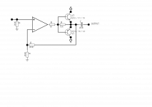
Note that in (1.), buffer stage gm still varies a lot with output swing, and distortion would accordingly be expected to be a fair bit worse than with a "real" AB buffer.
In (2.), 470R resistors seem rather a factor of 10 low. (Remember that the opamp has to drive 470R || 470R || (Rload * transistor beta).) I also very much doubt that the opamp is going to appreciate the lack of any DC path to the output; I would expect it to latch up. One may have to grudgingly accept single-side driving, though an additional resistor as seen in (1.) (but with like 10k or so) may well fix this. Without any output series resistance at all (and no small cap from OP out to -in), stability may be questionable, too.
I do agree (2.) is the way to go, with the bugs worked out. Though it has to be said that a buffer stage with two unity gain NJM4556s in parallel with 2R2-ish combining resistors also has something going for it. A fair bit simpler to implement, for one. +/- 15V may have them get rather warm driving low-impedance loads though, somewhat less may be more appropriate.
Diodes VD should see thermal coupling to respective output transistors; solder as directly to leg as possible.
Re: the OP's circuit:
There's no way in hell this "balanced" input is going to work. Read up on how those look. Chances are it'll end up using some instrumentation amplifier type IC (usual TI INAs / THAT SSMs). Besides, a 200 ohm mic input does not have a 200 ohm input impedance. But INA datasheets should show that, too. The one downside of INAs is that they usually don't do negative gain, and you can use some of that with pro-level inputs.
LF347s are awfully old buggers. They're like TL074s with less pathetic output drive capabilities (especially at lower voltages) and as such probably more useful as an all-round opamp. In any case, unless there are very compelling reasons to go with a quad, I would suggest sticking with duals. That'll give you many more interesting types to choose from. Most quads are old and not particularly good. Singles tend to be worth it only occasionally, but there are a few interesting types like OPA627 or the trusty LF356. (BTW, the LF357 shown in the schematic - a decompensated LF356 - seems to have been EOL'd years ago.)
I'd recommend getting the ground symbols sorted out. In a pro audio device you are likely to find signal ground, chassis ground and protective earth, and as such correct nomenclature is essential.
Speaking of grounding, XLR pin 1 should go to chassis ground rather than signal ground. There's nothing inherently magical about chassis ground, but it provides a separate path back to star ground. Properly joining chassis ground and signal ground is a bit of a science in itself; it usually involves a parallel RC combo. (I would do something like connecting chassis ground to PE, and then branching out to signal star ground via something like 10R || 10nF.)
IC2A/B circuitry still doesn't look right.
Last edited:
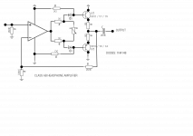
Another go at the h/phone amp.
Gets rid of the nasty electrolytics
DC path for the opamp output.
Still not certain about the resistor values, too tired to do lots of sums! 🙁
I agree that the I/P stage isn't pro-audio. I assumed that it was required for amateur use, also not balanced mic inputs.
At the very least a quiet opamp should be used here. It is possible to make a balanced input amp with a normal opamp.
Attachments
- Status
- Not open for further replies.
- Home
- Amplifiers
- Headphone Systems
- Personal Monitor System