the thd for this circuit has been measured at 10KHz 10W as 0.002%, however my in my sims i get 0.03% 😕
https://www.diyaudio.com/forums/group-buys/307077-peeceebee-v4-gb.html
https://www.diyaudio.com/forums/group-buys/307077-peeceebee-v4-gb.html
Attachments
The circuit has two regulators of current sources and one quiescent current of the output stage.
Have you changed (configured) them?
Have you changed (configured) them?
Peeceebee V4H
Hi
I have been looking at the peeceebee V4H Rev1. Like you, I cannot get the distortion numbers to match what is specified for this amp.
At 1 KHz, it seems to matct, but at 10KHz, my LTSpice simulation is way off. When trying to simulate open loop gain, I get ~ 57dB with a 5 ohm load.
Without load ~ 58dB. Phase margin is ~ 88.6° and gain margin ~ 28.2dB
I think that ~ 58dB seems somewhat low to achive 0.005% THD while delivering 100W/10KHz into 5 ohm's.
Can someone please verify that my open loop gain simulation is correct?
I have tried with different mosfet models from this forum. None come close the specified values.
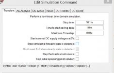
The attached schematic contains all the models used, and is it setup to run sims for 1/10/100 watts into 5 ohms at 100/1KHz/10KHz.
I have added the distortion results to each mosfet model.
To run the bode plot, comment out the SINE text and uncomment the BODE text.
Regards
Jorgen
Hi
I have been looking at the peeceebee V4H Rev1. Like you, I cannot get the distortion numbers to match what is specified for this amp.
At 1 KHz, it seems to matct, but at 10KHz, my LTSpice simulation is way off. When trying to simulate open loop gain, I get ~ 57dB with a 5 ohm load.
Without load ~ 58dB. Phase margin is ~ 88.6° and gain margin ~ 28.2dB
I think that ~ 58dB seems somewhat low to achive 0.005% THD while delivering 100W/10KHz into 5 ohm's.
Can someone please verify that my open loop gain simulation is correct?
I have tried with different mosfet models from this forum. None come close the specified values.
The attached schematic contains all the models used, and is it setup to run sims for 1/10/100 watts into 5 ohms at 100/1KHz/10KHz.
I have added the distortion results to each mosfet model.
To run the bode plot, comment out the SINE text and uncomment the BODE text.
Regards
Jorgen
Attachments
the thd for this circuit has been measured at 10KHz 10W as 0.002%, however my in my sims i get 0.03% 😕
PeeCeeBee V4 GB!
The accuracy of simulation, depend on the accuracy of the components model. In this forum, we used components model from Bob Cordell and Ian Heglun's for mosfet that include k-sub threshold.
Hi.
I also could not come even close Bimo, regardless of models used.
Have you tried my schematic from previous post?
Regards
Jørgen
I also could not come even close Bimo, regardless of models used.
Have you tried my schematic from previous post?
Regards
Jørgen
Hi ctrlx,i tried b.c. and i.h. models but still get around 0.03%
Attached v4 sim with IH laterals giving 0.03% at 10W 10kHz.
And it gives 0.003% at 10W with 1kHz.
I think these THD sim figures are in the right ball-park for this topology.
Differences in models don't appear to make more than a factor of 2 difference in the 10kHz 10W THD. But there is a factor of 10 difference between measured and sim.
So, has anyone else (other than shaan) measured the v4 THD at 10kHz 10W 8R?
One thing to watch is the THD bandwidth. To get the first 10 harmonics with 10kHz (like our sims) you would need a sample rate of 196kHz or more.
Attachments
- Home
- Amplifiers
- Solid State
- peeceebee v4 distortion simulation