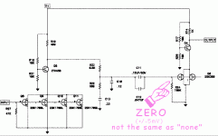
I am trying to diagnose a persistent but intermittent problem in the right channel that drops out. What should the voltage be between C11 and R24? I measure some voltage on the channel that works, but none whatsoever on the right channel. All the voltages on the test points in the Fig. 5 schematic are correct and moving upstream from C11 I also don't find any differences. The difference appears at C11 and R24. Thanks.
What is "none whatsoever"? Does the meter crap-out? Blank display? OL?
Intermittent drop-out is usually a bad solder joint, switch/pot/plug contact, PCB, occasionally such a fault inside a cap or resistor (yes, even a FET). An obscure cause is police (do they have them in Antarctica?) or cell/wifi signals, not directly audible, but strong enough to temporarily knock the bias out of bounds.
Intermittent drop-out is usually a bad solder joint, switch/pot/plug contact, PCB, occasionally such a fault inside a cap or resistor (yes, even a FET). An obscure cause is police (do they have them in Antarctica?) or cell/wifi signals, not directly audible, but strong enough to temporarily knock the bias out of bounds.
Attachments
Thanks for the reply! It's not intermittent for short periods, but long periods. I turn it on, it works for half an hour, then the right channel dies and stays dead for days. Then one day I turn it on, and it works again for a while, and it's not the cable, the speaker, the source, etc.
So according to your gif the point between C11 and R24 should be 0 +/- 5 mV, and that's what I have in both channels. The left channel that works fluctuates between .002 and .012 and the right channel is always .000. I thought that was a relevant difference, but I guess it isn't. I guess C11 might leak a little?
I wish I knew more about how to diagnose this. As I said, all the voltage points noted in figure 5 measure properly, and I also more or less randomly measure other points to see if I can find a difference. This is what puzzles me is that all the voltages seem fine in both channels from pad 1 to C9, and C9 is fine. There is continuity from input and output jacks to the board. Where or how else should I look?
You should do signal tracing with a scope when the problem happens.
Play an LP or test signal and follow the signal through the circuit from the input to the output.
The problem is located where the signal first goes away. The problem may or may not
also affect the DC voltages in the circuit. The parts themselves are unlikely
to cause such a problem, but there could be bad connections.
Last edited:
My mV numbers are quesses. There is always some small gate current, which will make a small voltage in a large resistance.
If it is at DEAD Zero, you may have a Short. Solder-blob. Wire trimming. I once had a goofy PC, turned it over and beat it, metal swarf fell out of the card-clots.
Such a short will not noticeably affect other DC voltages but will short-out the signal.
If it is at DEAD Zero, you may have a Short. Solder-blob. Wire trimming. I once had a goofy PC, turned it over and beat it, metal swarf fell out of the card-clots.
Such a short will not noticeably affect other DC voltages but will short-out the signal.
Well, after poking around in it, I assembled it and now it works and it's been working for a while now.
It's too cumbersome to get the oscilloscope, record player, etc. in one place. But I could run the output of a cd player into the Pearl Phono and trace the signal with the scope. If I keep the volume is that ok?
It's too cumbersome to get the oscilloscope, record player, etc. in one place. But I could run the output of a cd player into the Pearl Phono and trace the signal with the scope. If I keep the volume is that ok?
- Home
- Amplifiers
- Pass Labs
- Pearl Phono R1 Voltage question
