Hello,
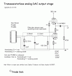
I have found a jukka tolonen 6SN7 tube output stage for PCM56 DAC on triode dick site (http://members.home.nl/triode.dick/dacuitgang.html).
I have a pcm56 DAC (Zeuslab pureIII sk dac http://www.zeuslab.newmail.ru/pure_III.htm) and want to put this output stage in it.
On the schematic the supply voltage is 300V.
Does somebody can help me and give me a good and simple (whitout chokes) PSU schematic for this 300V B+ ?
Thank you very much to all.
Pascal.
Attachments
Hello ,
I`m using the same design , but without an analog filter on Denon DCD595 - PCM61P
My tubes are 6N23P-EV and really sound great with 260V and 12mA. I have tried PCC88, 6N1P , E88CC and one great 6DJ8 for this job. They all sound well , with some differences.
It will be better to use a 1uF or greater decoupling capacitor , espetialy if your amplifier have low input impedance. This is something you will be able to test with ease🙂
The project is great for starting , but have some difficulties. As example the tubes must be with very low microphonics. Your power supply must be very good to reduce noise. I personally spend a lot of time fighting with microphonics. Currently using tube dampers , floating sockets and matched tubes.
The second problem is that 100 ohm resistor for the I/V conversion is a bit too much. I prefer using 50 ohms or so. Last week I bought 2 old line transformers that I will use for the I/V convertion.They are 600:75000, that mean 1:11 turns ratio. I assume that they will lower the resistor value seen by the dac.And it will work as a analog filter too 🙂
It will look like this:
About the power supply. You can use snubber design , with several RC networks. But you must calculate the current that you will need , becose it will affect the power sopply design greatly
Good luck ! 🙂
I`m using the same design , but without an analog filter on Denon DCD595 - PCM61P
My tubes are 6N23P-EV and really sound great with 260V and 12mA. I have tried PCC88, 6N1P , E88CC and one great 6DJ8 for this job. They all sound well , with some differences.
It will be better to use a 1uF or greater decoupling capacitor , espetialy if your amplifier have low input impedance. This is something you will be able to test with ease🙂
The project is great for starting , but have some difficulties. As example the tubes must be with very low microphonics. Your power supply must be very good to reduce noise. I personally spend a lot of time fighting with microphonics. Currently using tube dampers , floating sockets and matched tubes.
The second problem is that 100 ohm resistor for the I/V conversion is a bit too much. I prefer using 50 ohms or so. Last week I bought 2 old line transformers that I will use for the I/V convertion.They are 600:75000, that mean 1:11 turns ratio. I assume that they will lower the resistor value seen by the dac.And it will work as a analog filter too 🙂
It will look like this:
An externally hosted image should be here but it was not working when we last tested it.
About the power supply. You can use snubber design , with several RC networks. But you must calculate the current that you will need , becose it will affect the power sopply design greatly
Good luck ! 🙂
PTSOUNDLAB said:
Does somebody can help me and give me a good and simple (whitout chokes) PSU schematic for this 300V B+ ?
Thank you very much to all.
Pascal.
Hi Pascal
Have a look at the PS design of tube output stage by Lukasz Filus at www.lampizator.eu. He uses 6N1P with 180V but you can design 300V supply with right transformer & CRC after that. His PS design is very sophisticated & has no crosstalk or any other problems as shown in various detailed measurements he has on the site.
I built his tube output stage for my Arcam 70.2 TDA1541 S1 dac & result has been fantastic. The CD sound is getting closer & closer to my EMT930 with this mod & superclock,psu,regulators etc.
As mentioned by Blackblood, you need to find out the maximum voltage compliance of your DAC & make sure you stay below that figure as most of these current output dac distort if they see too much voltage at the output pins.
BlackBLOOD said:
It will be better to use a 1uF or greater decoupling capacitor , espetialy if your amplifier have low input impedance. This is something you will be able to test with ease🙂
It will look like this:
An externally hosted image should be here but it was not working when we last tested it.
Hi Blackblood
Could you elaborate please how you mean to test easliy for input impedance of the amp? Thanks
Also I presume when you put in the line transformers and reduce the size of iv resistor even furthur, you will still keep the tube output stage. Most of designs where only a transformer is used with the resistor, apparently dont do as well when compared to a tube output stage. It will be interesting to see what you think if you go down that route and do an A-B comparison.
Best regards
Fib
Actually my idea was to test different capacitor sizes and that way test if they preform well with the amplifier input impedance.
IMHO if you make a simulation of your amplifier , you can calculate your expected input impedance. TubeCAD is doing it OK, as an example.
Well for me the tube stage is too important. My transformer is only 1:11 and the level will be to low if i use small resistor for less distortion and no amplifier elements. The output impedance will be high too.
I prefer to have one SRPP stage +27db amplification in my case(if i remember it right) and output impedance around 1,5k.
Later i can use another transformer to couple the tube stage with the amplifier stage. Its not cheap , but it will be probably better than a coupling capacitor...
Thanks Blackblood. Thats exactly what I thought you meant by trying out different cap sizes.
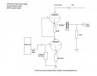
Have you found a suitable circuit to use a transformer to replace the output coupling cap for srpp/anode follower stage (which I have)? Andrea Ciuffoli has used Lundahl 1660 AM for his single ended tube output stage here
http://www.audiodesignguide.com/DacEnd/index.html
However, even after looking most places I havent found how to use it in my circuit which is as below. I wonder if you have any ideas.
Best regards
BlackBLOOD said:
Later i can use another transformer to couple the tube stage with the amplifier stage. Its not cheap , but it will be probably better than a coupling capacitor...
Have you found a suitable circuit to use a transformer to replace the output coupling cap for srpp/anode follower stage (which I have)? Andrea Ciuffoli has used Lundahl 1660 AM for his single ended tube output stage here
http://www.audiodesignguide.com/DacEnd/index.html
However, even after looking most places I havent found how to use it in my circuit which is as below. I wonder if you have any ideas.
Best regards
Attachments
🙂 There is no point on putting output transformer on a SRPP circuit. The idea of the SRPP is that it lowers the output impedance. The output transformer will do the same.
The idea is to use in a normal gnd cathode design , with some triode with good amplification and big enough voltage output. The transformer will step it down , and reduce the impedance as well. The other point is that we get another analog filter , so the High frequency noise from the dac will be filtrated even better.
I assume that with those two analog filters we will be able to remove the Oversampling Filter without suffering the negatives of High frequency distortion passing to the next stage.
IMHO they are many other advantages in using a transformer but , my knowledge is not enough to explain them...
Oops!
Thanks Blackblood for clearing that up. 🙂
My main reasong for looking for a transformer output was to avoid using a coupling cap. I am still learning the ropes of tube circuits & guess will get there in end. For the moment I am going ahead with using a good quality capacitor after the tube stage.
Best regards
- Status
- Not open for further replies.
- Home
- Source & Line
- Digital Source
- PCM56 DAC with 6SN7 output stage