I've got a couple of PCL805s laying around and I've got this single speaker from an old radio so I thought I'd make me a simple mono SE bookshelf/tabletop "yellbox" that would combine both stereo channels and deliver enough power a small room/office (as it obviously did in its original incarnation, the radio receiver) for a PC.
Since I don't have a suitable SE output transformer I decided to finally explore the interesting world of parafeed 🙂
I deliberately tried to limit the input to 15-20 Hz minimum in order to avoid core saturation; the speaker can't reproduce anything below 50 Hz anyhow, 40 Hz is pretty much inaudible.
However as I was also trying to limit HF response, I encountered a problem: I only found one datasheet for ECL/PCL805 and it doesn't list triode capacitances (specifically: Cga and Cgk) so that I could calculate the grid stopper value accordongly. Anyone happen to have a datasheet which shows these two values ?
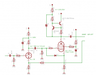
I omitted input connectors because my version will use a summing junction which could confuse people who might stumble across this thread and didn't read the entire text, plus OPT is missing in the picture because I couldn't be bothered to look up a suitable symbol 🙂 It should be pretty obvious nevertheless, input is on the left, output and NFB input are on the right. NFB is taken from OPT's secondary and was calculated to drive speaker to full 2.2W with 0.316 V(RMS) input, allegedly "consumer audio line level". Anybody care to verify my maths ? I shall be much obliged ! 😀
Unless schematic says otherwise all resistors are 0.25W and all capacitors are 300+V type.
Power supply section isn't shown but all voltages are marked, V+ (= B+) should be 270-275V or thereabouts for numbers to work out.
Power transistor in CCS can be any high voltage type (300V or higher rating) that can dissipate constant 8W, it could even be a N-channel MOSFET in place of NPN BJT, just don't forget about sufficient heatsink !!!
Pentode section cathode resistor should really be adjustable so that Vg = -13V can be "dialed in".
Drawing pictures is easy, now to find enough time to move my butt and build this thing 🙄
Since I don't have a suitable SE output transformer I decided to finally explore the interesting world of parafeed 🙂
I deliberately tried to limit the input to 15-20 Hz minimum in order to avoid core saturation; the speaker can't reproduce anything below 50 Hz anyhow, 40 Hz is pretty much inaudible.
However as I was also trying to limit HF response, I encountered a problem: I only found one datasheet for ECL/PCL805 and it doesn't list triode capacitances (specifically: Cga and Cgk) so that I could calculate the grid stopper value accordongly. Anyone happen to have a datasheet which shows these two values ?
I omitted input connectors because my version will use a summing junction which could confuse people who might stumble across this thread and didn't read the entire text, plus OPT is missing in the picture because I couldn't be bothered to look up a suitable symbol 🙂 It should be pretty obvious nevertheless, input is on the left, output and NFB input are on the right. NFB is taken from OPT's secondary and was calculated to drive speaker to full 2.2W with 0.316 V(RMS) input, allegedly "consumer audio line level". Anybody care to verify my maths ? I shall be much obliged ! 😀
Unless schematic says otherwise all resistors are 0.25W and all capacitors are 300+V type.
Power supply section isn't shown but all voltages are marked, V+ (= B+) should be 270-275V or thereabouts for numbers to work out.
Power transistor in CCS can be any high voltage type (300V or higher rating) that can dissipate constant 8W, it could even be a N-channel MOSFET in place of NPN BJT, just don't forget about sufficient heatsink !!!
Pentode section cathode resistor should really be adjustable so that Vg = -13V can be "dialed in".
Drawing pictures is easy, now to find enough time to move my butt and build this thing 🙄
Attachments
Curious, the Telefunken and Philips sheets both avoid triode capacitance specs.
But the triode is very closely specified to the ECC81, almost same mu, curves etc.
Philips spec for ECC81:
Cga 1,6pF
Cgk 2,3pF
could try the stopper value to suit these capacitances & measure the HF rolloff, then tweak stopper value to shape it just right.
But the triode is very closely specified to the ECC81, almost same mu, curves etc.
Philips spec for ECC81:
Cga 1,6pF
Cgk 2,3pF
could try the stopper value to suit these capacitances & measure the HF rolloff, then tweak stopper value to shape it just right.
2.2W out of a tube with an max plate dissipation of 10.5W, a B+ of 275VDC, and an SS CCS seems really high to me. I would expect that out of maybe a choke loaded parafeed, but not SS. Is that printout from a simulator?
Same tube:
http://http://www.dmitrynizh.com/6f5p-set-impl.htm
interesting writeup, esp wrt distortion spectra.
http://http://www.dmitrynizh.com/6f5p-set-impl.htm
interesting writeup, esp wrt distortion spectra.
Last edited:
2.2W out of a tube with an max plate dissipation of 10.5W, a B+ of 275VDC, and an SS CCS seems really high to me. I would expect that out of maybe a choke loaded parafeed, but not SS. Is that printout from a simulator?
No, that is merely an estimate based on plate curves. 220V & 80 mA peak-to-peak swing with 14V p-t-p on g1, 220V * 80 mA / 8 = 2.2W(RMS). Correct ? It will be lower in practice and that's precisely what I want (the speaker can handle up to 2W !).
PCL805 is an oddball tube, very high current at relatively low voltage. The highest 2600R loadline touches the 8W anode dissipation curve at 145V @ 55 mA, 10.5W at 165V @ 48 mA. Assuming negligible drop in CCS this means under 300V B+ is needed for CCS load.
I think I'm going to add adjustable PSU noise injection ("Ultrapath") to first stage.
@Rod: this is what I used as a reference, 10-20K would cut off well above audio band but also well under MW RF.
@mach1: "the page cannot be displayed" 🙁
Last edited:
Yagolar, thanks for the corrrcted URL ! It looks like this author went for triode connection. Alas triode curves for pentode section are nowhere to be found but he did make me look at the datasheet of the Russian tube (mine were manufactured by EI Nis & Philips) which does show input capacitances. They appear to be slightly higher than those of ECC81, but not by much (~10%), so my guesstimate was correct 🙂
It is missing input triode capacitances and triode curves of pentode portion of the tube. This is the one I was referring t when designing this amplifier.
This is close to specs of Russian 6F5P on the link you provided earlier, these suggest ~60 pF input capacitance so 10-20K grid stopper is perfect 🙂
This ? http://www.tubes.mynetcologne.de/roehren/daten/ecl85pentode_as_triode.pdfAlas triode curves for pentode section are nowhere to be found
- Status
- Not open for further replies.
- Home
- Amplifiers
- Tubes / Valves
- PCL805 parafeed SE idea + question