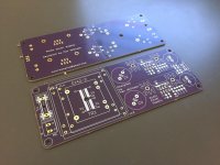
I recently completed a couple of projects and have some PCBs left over. I have two of each. They are from OSHPark and have purple soldermask over bare copper (SMOBC) and an ENIG (Electroless Nickel Immersion Gold) finish.
I'm selling them all at cost. For postage add 2 euros.
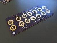
Input Selector - €10
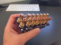
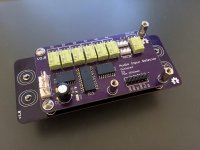
RCA Board - €13 each
MDAC Attenuator - €5 each
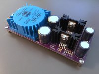
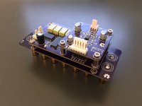
Dual TPS7A330 +/- PSU - €17 each
I'm selling them all at cost. For postage add 2 euros.
Input Selector - €10
- 6x inputs
- Mute for the output
- SPI controlled, easy to control, I will provide example Arduino code.
- Uses latching relays so no constant current draw (mute is not latching, obviously)
- Uses high quality Panasonic GQ relays (AGQ)
- BoM provided
- Matches the RCA board perfectly
RCA Board - €13 each
- 6 inputs, 1 output
- Made to match the input selector but could easily be used separately.
- Designed for CMC 816 RCA sockets, they can be soldered directly on to the PCB and are easy to find on both eBay and Aliexpress etc.
MDAC Attenuator - €5 each
- 65536 linear steps (16bit)
- Any gain possible, set by opamp and resistors
- Excellent performance (better than PGA2320 in my measurements)
- Can drive headphones
- Compact
- Identical design to the one used in my preamp. Details, measurements etc are here.
- SPI controlled, easy to control, I will provide example Arduino code.
- Can be mounted on the top of the above input selector but also works fine alone.
- BoM provided
Dual TPS7A330 +/- PSU - €17 each
- Design, layout etc is here
- Works well in my testing.
- BoM provided
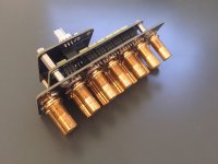
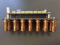
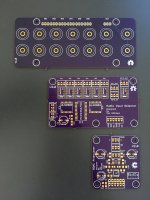
Photos of the relay board and input selector showing how they fit together. They would also work fine separately too.
Attachments
Bump.
MDAC PCBs are gone.
There is a 1 input selector and RCA board left.
Power supply PCBs are still available.
MDAC PCBs are gone.
There is a 1 input selector and RCA board left.
Power supply PCBs are still available.
Hi doneganm,
Sorry for the late reply, it seems email notifications are unreliable these days??
Anyway, yes, I have couple left.
Sorry for the late reply, it seems email notifications are unreliable these days??
Anyway, yes, I have couple left.
Hi Max,
Sorry for not replying. All of my projects are currently on hold as we are moving to HK in Jan. However, being close to the Pearl River Delta manufacturing / economic hub could prove very interesting, as I should get easy access to all of the electronic goodies in China.
I'm still committed to finishing this project when we've settled in.
What I've done so far:
Raspberry Pi with a USB CD player, Mamboberry LS DAC. Hardwired USB control via a Teensy 3.2 arduino board, rotary encoder with switch, RTC, infrared with 256x64 OLED for displaying track information and an alarm clock. The raspberry pi has a really tiny 480GB SSD attached and the CD player is set up to pipe directly through I2S to the DAC. It sounds pretty good. I use moode audio on the raspberry pi and I've written programs to display CD track info (after DB lookup) on the OLED, plus various other info and also to allow IR control of everything on the raspberry pi via the arduino.
The next step was to add in a power amp and input selection. I've got a class A headphone amp and decided on a tripath power amp. So thats two outputs and I'll need about 3 or 4 inputs, plus attenuation.
I think your attenuation circuit is a good match, but on closer inspection I think the input / output selector wouldn't work for what I need (2 outputs). I would be very keen to see the source schematic and layout for the input / output selector so I can change it to have two outputs. However, I understand if it's not for sharing.
Martin.
Hi Martin,
OK no worries. Sounds like an interesting project.
I share all my designs including layout and schematic files. You can find them in this thread:
http://www.diyaudio.com/forums/anal...-6-input-selector-mdac-attenuator-ir-etc.html
Good luck with the move, sounds fun!
OK no worries. Sounds like an interesting project.
I share all my designs including layout and schematic files. You can find them in this thread:
http://www.diyaudio.com/forums/anal...-6-input-selector-mdac-attenuator-ir-etc.html
Good luck with the move, sounds fun!
- Status
- Not open for further replies.