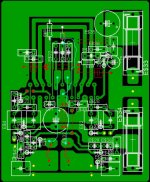
I have problems with my TDA8920BJ (non-smd version). At about 10W of output power overcurrent protection starts to work. I've tried almost everything except changing the PCB and I think this is the problem. I have designed single sided PCB and I had a lot of compromises to make (capacitors are not close enough to chip, output inductors are not shielded and are close to inputs...).
I would be very grateful if somebody could give me PCB layout which was tested and works, because I have spent too much time designing and making PCB-s, that dont work (5 pieces).
Layout can be double sided.
If anyone wants I can attach my layout if I can find it. Last time I was designing PCB was almost a year ago, then I gave up working with this IC-s and I started again this week
Thanks
Can you give us any details on the supply you're using? What are the rail voltages unloaded and while the amp is putting out around 10W?
That chip has a bunch of protection provisions. It might not necessarily be the over current protection that is causing your amp to cut out.
That chip has a bunch of protection provisions. It might not necessarily be the over current protection that is causing your amp to cut out.
Im using homemade switching power supply which has regulated both rails. Voltage is +/- 25V. I measured the voltages with load of 200W but they stay the same
I tried with standard supply (trafo, greatz, two capacitors) but the problem stays the same
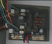
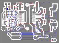
At the picture is top view of finished PCB.
At left are air inductors, but I tried also with toroide inductors from old computer power supply, and with some other inductors, but problem was always the same
I tried with standard supply (trafo, greatz, two capacitors) but the problem stays the same
At the picture is top view of finished PCB.
At left are air inductors, but I tried also with toroide inductors from old computer power supply, and with some other inductors, but problem was always the same
Attachments
The datasheet mentions something about a stabilizer output voltage (the STABI pin) and that it should be around 12V typical with a minimum of 11V and a max of 15V. How does the STABI voltage look on your amp unloaded and when putting out 10W?
Since you said the amp does the same thing with both types of supply, you're probably right that the overcurrent protection is being tripped because of output voltage and current spikes due to the PCB layout.
Do you have access to an oscilloscope to probe the pwm outputs and see exactly what's happening as you increase the output power? That's really the only way to tell for sure, unless you want to try the AM radio test. Bringing an AM radio in the vicinity of your amp will basically kill its reception if you're having EMI issues due to layout.
How do you know that these air inductors are of the right value? A too small inductor value will trip the overcurrent protection due to increased current ripple. Also, you should keep these air-cored inductors away from the PCB.
Also, how did you get these ICs? The datasheet that I have doesn't even seem to tell about that package option!
Also, how did you get these ICs? The datasheet that I have doesn't even seem to tell about that package option!
Eva, you can the most recent datasheet here: http://www.semiconductors.philips.com/acrobat_download/datasheets/TDA8920B_2.pdf
The inductors may not be spot on, but they certainly look to be more than 15uH.
Also, it's hard to tell from the photo, but in some areas it looks like the soldered lands are close to shorting out.
The inductors may not be spot on, but they certainly look to be more than 15uH.
Also, it's hard to tell from the photo, but in some areas it looks like the soldered lands are close to shorting out.
With no input, the STABI voltage is 13.27V. When protection is reseting amp, voltage is 12.17V. So I think this is OK
I have osciloscope, its around 25 years old, but works fine. I measured PWM output and I get something similar to square vaweform - left angles are not sharp. Right vertical line is moving left and right with music. Left line doesnt move
Eva:
I think you are right. Instead of 4 ohms I connected 10ohm resistor and I couldnt get the protection to work
I didnt measure inductance. I wound them by instructions from a program called "air core calculator" or something simmilar. Anyway I would rather have inductors with ferite core, because they are smaller.
I have tried with toroide inductors from old PC power supplys but they were overheating. Protection also worked.
Would be inductors from old PC motherboards better? If I remember correctly they work at 500kHz
There is not any shortcut at PCB. I checked twice.
Primoz said:I have osciloscope, its around 25 years old, but works fine. I measured PWM output and I get something similar to square vaweform - left angles are not sharp.
How much voltage overshoot is there on the waveform and how long does the ringing last compared to the switching period?
Not any inductor will work on that circuit. Toroids may overheat depending on the material and the number of turns (increase turns until the temperature is reasonable, altough that may produce a too high inductance value). Inductors from PC motherboards and even from PC power supplies are likely to have too low inductance. You should build some test circuit to allow you to apply constant voltage pulses to your inductors and measure current rise slope and see saturation with the oscilloscope (there is almost no other way to measure iron powder inductors due to their leakage, as sine measurement is likely to produce erratic results).
Capacitance between turns is evil due to the very fast swiching transients, and your air cored inductor is likely to be suffering from that, as it's made of two layers and both ends of the coil are on the same side. Suitable inductors should be made with only a single winding layer (two or more identical layers made with thiner wire may be used to get the required turn count with a smaller winding width, but never splitting the same winding in two or more series layers).
Capacitance between turns is evil due to the very fast swiching transients, and your air cored inductor is likely to be suffering from that, as it's made of two layers and both ends of the coil are on the same side. Suitable inductors should be made with only a single winding layer (two or more identical layers made with thiner wire may be used to get the required turn count with a smaller winding width, but never splitting the same winding in two or more series layers).
In my case the core of toroids was producing heat. Wire was thick enough. I had 15 turns on torroid with oudside diameter of 27mm. Hole inside has diameter14mm. Color is yellow. At one side it is white
My air cores have 3 layers, so this is a problem. Its impossible for me to use long air core with only one layer because I dont have enough space in my amplifier housing
Does Coilcraft have any suitable inductor for my amplifier? I was searching but I dont know what I really need. I know just that inductance should be 22uH and frequency 400kHz.
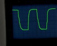
BWRX: Sorry but I dont have osciloscope for long time and I dont know what ringing and simmilar things are. Waveform is very clean without any spikes. Difference between + and - amplitude at PWM output is 50V - same as supply voltage, so I think this is OK.
There is a picture how waveform looks like. You wont believe how much effort I put in this picture. Because I dont have digital camera, I put osciloscope at scanner 😀 . Because waveform was too hard too see, I edited picture with MS Paint. Waveform at osciloscope looks better than edited.
My air cores have 3 layers, so this is a problem. Its impossible for me to use long air core with only one layer because I dont have enough space in my amplifier housing
Does Coilcraft have any suitable inductor for my amplifier? I was searching but I dont know what I really need. I know just that inductance should be 22uH and frequency 400kHz.
BWRX: Sorry but I dont have osciloscope for long time and I dont know what ringing and simmilar things are. Waveform is very clean without any spikes. Difference between + and - amplitude at PWM output is 50V - same as supply voltage, so I think this is OK.
There is a picture how waveform looks like. You wont believe how much effort I put in this picture. Because I dont have digital camera, I put osciloscope at scanner 😀 . Because waveform was too hard too see, I edited picture with MS Paint. Waveform at osciloscope looks better than edited.
Attachments
Eva:
Do you have any link with detailed instructions?
So the problem is then not in PCB but in inductors?
You should build some test circuit to allow you to apply constant voltage pulses to your inductors and measure current rise slope and see saturation with the oscilloscope (there is almost no other way to measure iron powder inductors due to their leakage, as sine measurement is likely to produce erratic results).
Do you have any link with detailed instructions?
So the problem is then not in PCB but in inductors?
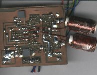
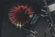
I tried with green inductor with one side painted in blue. I have no idea what the inductance is, but it is not overheating . It has 25 turns and same diameter as yellow ones
Now protection starts only if both channels are connected. If is connected only one, this doesnt happen. If I connect only one channel I can get 100W. If I connect both I cant get more than 10W/channel 😕
Picture of new inductor (only green wire connected). I have several kilograms of different inductors. Problem is just that I dont know their specifications
Attachments
Problem solved!
I added some 100nF capacitors and 47uF between Vddp and Vssp and with thick wire connected ground around output filters to ground around SGND pins of TDA.
Now I get 90W/channel with both channels connected
Thanks for your help.
I added some 100nF capacitors and 47uF between Vddp and Vssp and with thick wire connected ground around output filters to ground around SGND pins of TDA.
Now I get 90W/channel with both channels connected
Thanks for your help.
So all this time it was just a supply decoupling issue... At least it was a simple fix!
Any opinion on how your implementation of the TDA8920 sounds?
Any opinion on how your implementation of the TDA8920 sounds?
I only tried with subwoofer, so I cant tell. At friday I m going to connect normal speakers and compare the sound of TDA8920 and TDA1514A.
- Status
- Not open for further replies.
- Home
- Amplifiers
- Class D
- PCB layout for TDA8920BJ wanted