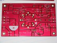
I designed a somewhat updated PCB for Gary Pimm's CCS & Solid State Pentode circuits. I wanted to make the changes for a couple reasons:
1) Move both transistors to the same side and put them on a standard (1") center.
2) Provide for creating both the CCS & SS pentode circuit with no modifications
3) Provide for screw terminals
And most importantly, recreate it in Eagle and at a standard size for Seeedstudio and Itead's PCB service, which gives you 2" x 2" PCB's with silk & mask both sides for all of a buck a board.
I started building out a set for a headphone amp:

I need to make a few tweaks, and before I could post the Eagle and/or Gerbers, I have to get permission from Gary, whose email no longer works. So if anyone has a contact for him please let me know or point him to this post. Thanks!
1) Move both transistors to the same side and put them on a standard (1") center.
2) Provide for creating both the CCS & SS pentode circuit with no modifications
3) Provide for screw terminals
And most importantly, recreate it in Eagle and at a standard size for Seeedstudio and Itead's PCB service, which gives you 2" x 2" PCB's with silk & mask both sides for all of a buck a board.
I started building out a set for a headphone amp:
I need to make a few tweaks, and before I could post the Eagle and/or Gerbers, I have to get permission from Gary, whose email no longer works. So if anyone has a contact for him please let me know or point him to this post. Thanks!
How do you mount that? I see mounting holes at 2 corners, but none and no room for any at the other 2 corners.
The board is rather light. It's designed for the main two TO-220 transistors to be mounted to a case or otherwise secured heatsink, not for small unsupported or pcb-mounted heatsinks. Because of this you can really mount it with only one or two screws (on the left side) or honestly with none, as long as the heatsink is secure.
Generally the PCB will stick out at a 90 degree angle from the heatsink surface, or the transistors can be mounted on the bottom and bent out sideways, and the mounting holes can be used with small standoffs and screwed into the heatsink surface as well.
There are some examples of this on Gary's page: Here is the newest member of the CCS family You can see down below that assuming the heat load isn't too great, you can often just use the case itself as a heatsink.
Interested in these boards. I have some other CCS boards which I have modified for use as SS Pentode & have populated the boards but haven't had the time or large enough heatsinks to try them.
Has anybody actually built a SS Pentode amplifier? I need some motivation to finish this, so let's hear some reports about this amp.
Has anybody actually built a SS Pentode amplifier? I need some motivation to finish this, so let's hear some reports about this amp.
I built a single channel differential test amp that is basically the driver stage of the SS Tabor, for use with headphones. The measurements even with a really budget Edcor transformer were very good. 2nd Harmonic - 75db, 3rd -67db, 4th -86db, 5th+ -100db or lower. This was at ear-destroying power levels. Total THD in rightmark was 0.074, IMD&N was 0.100. Dynamic range was 88db, the limiting factor mainly being 60 & 120hz hum from my choke-input supply. And all this was on a rather budget USB 'sort of' pro audio card, which probably contributes about 10-20% of the distortion and only has about 92db dynamic range on its own anyway.
And this was on a breadboard with very, very long wires and the circuit built as the nastiest perfboard monstrosity ever. My biggest issue so far is the monstrous magnetic field produced by the choke-input supply coupling into the output transformers. Moving the transformers around with a scope on the output helped me find some 'dead spots' that I might be able to take advantage of in the final build, or just use a separate supply.
And this was on a breadboard with very, very long wires and the circuit built as the nastiest perfboard monstrosity ever. My biggest issue so far is the monstrous magnetic field produced by the choke-input supply coupling into the output transformers. Moving the transformers around with a scope on the output helped me find some 'dead spots' that I might be able to take advantage of in the final build, or just use a separate supply.
Last edited:
Interested in these boards. I have some other CCS boards which I have modified for use as SS Pentode & have populated the boards but haven't had the time or large enough heatsinks to try them.
Has anybody actually built a SS Pentode amplifier? I need some motivation to finish this, so let's hear some reports about this amp.
Lynn Olson wrote about it, he said it sounded like a very good Pentode amp but dead quiet.
I've heard Gary's amp several times. It's very good. Clean, natural, smooth, with real detail. About all you could want in an amp. Quiet, too.
There are some examples of this on Gary's page: Here is the newest member of the CCS family You can see down below that assuming the heat load isn't too great, you can often just use the case itself as a heatsink.
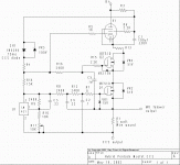
Sorry to drag up an ancient thread, but I have been given a couple of Gary Pimm CCS original PCBs, and I don't have the schematic. The link above no longer works.
Does anyone have the schematic for this PCB?
Thanks in advance,
Gary (not that Gary!)
Attachments
Here's a copy of the page in the posted link but the schematics don't appear to be the same circuit. (No LND150 on your board, no LM431 in schematic etc etc.) I think I might have saved a couple of his schematics on an old hard drive (in a box. . . . .somewhere 🙂 ) I'll see if I can find it.
Attachments
This is what I found. If it is for the same series it is probably for a later version as there's no Q2/C5 on your board. You'll have to check to be sure. Anyway, that's all I've got here. I hope it's of some use to you.
And here's the text that was with it on the original page:
"After studying Rev 3 for quit awhile I found that the main AC current leakage path was the drain-gate capacitance of Q1. The drain-gate capacitance of Q1 would couple into C2 and then go right out the bottom of the CCS.
With the adition of Q2 and C5 the leakage is now "captured" and routed back into the signal current at the source of Q1. The source of Q1 is the summing node of the CCS. The bias for Q2 is developed by adding a resistor in series with R4. Q2 and the pentode does not need a squeeky clean reference.
The addition of Q2 and C5 increased the performance from the 200M ohms and 3pf shunt capacitance of the Rev 3 circuit to 2G ohms and .15 pf shunt capacitance.
Listening tests confirm that the extra isolation is quite noticable."
Attachments
Latest Info on this Pimm amp?
From what those at this thread may have concluded so far, albeit in Gary Pimm’s absence, is the actual completed circuit likely to be some kind of voltage or current follower amp?
And if this is a follower output stage, how many wpc into 8 and 4 ohm loads, for how many volts input?
Based on their different designs, how would its performance differ from, say, the First Watt F4 amp?
See pp. 13, 14. http://www.firstwatt.com/pdf/prod_f4_man.pdf
- Status
- Not open for further replies.
- Home
- Amplifiers
- Tubes / Valves
- PCB for Gary Pimm's CCS & SS Pentode