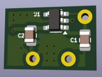
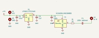
Hi! Want to share an idea about upgrading crystals to good oscillators. Here is a probe of such one, while studiyng KiCad. First one is for upgrade 2pin crystals in HC-49/US case (11.35mm x 5.00mm, 5mm spacing between legs). Capacitor C4 is optional and needed in cases where logic level is higher than 3.3V, in other cases we solder a jumper instead. Regulator voltage 1.8/3.3V need to be choosen depending to logic level, according to datasheet of IC. XO pin need to cut and I propose to use it hole as gnd for adapter and it's out need to be connected to XI pin/hole. I would be glad to receive useful advice regarding board design in KiCad.
Attachments

Last edited:
@jean-paul
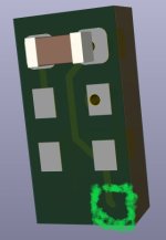
Please help, how to make such a pad without spacing to border of PCB ? Drawing filled zone always leave 0.5mm
Please help, how to make such a pad without spacing to border of PCB ? Drawing filled zone always leave 0.5mm
Attachments
Would have to draw myself to see what happens. If you send the file to me by PM I can look. I think you want at least one rigid angled pin of the output to the XTI on of the old oscillator and possibly an extra floating pad for a solid wire to GND as mechanical support.
BTW no ferrite bead?
BTW no ferrite bead?
Last edited:
How good are you thinking of? Reason I ask is the schematic you posted IME will at best give so-so results. Maybe better than stock, yet the underlying idea could probably be further developed. Depends on your goals....upgrading crystals to good oscillators...
Very nice hearable results in every stock device where I've changed such clocks. I'am not pretending on high-end market, but it is hearable a lot and cost few bucks and time to make it.How good are you thinking of? Reason I ask is the schematic you posted IME will at best give so-so results