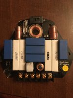
I have a passive crossover I was using in a car audio install. The tweeter was dropping to very low, muffled output... then would cone back at random times. Now it just stays at very Very low output. I hooked up the crossover to a different speaker and a different amp to isolate and confirmed it’s the crossover causing the issue. It’s a good one and I’d like to get it working again but don’t know where to start or what to look for. Capacitor gone bad maybe? I’ve got a ddm and general knowledge. I think I could do it with a little advice. Would appreciate any thoughts on it thanks!
Do you have it apart yet? A poor-quality solder joint is the most likely culprit.
A careful, thorough visual inspection may be all you need. Electronically, a passive crossover is not terribly complicated. Odds are there isn't even a Service Manual for it.
Good Luck
A careful, thorough visual inspection may be all you need. Electronically, a passive crossover is not terribly complicated. Odds are there isn't even a Service Manual for it.
Good Luck
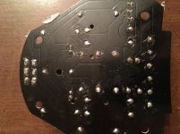
Photos (good quality, top and bottom of the board) would help us to help you.
Post #2 is likely correct. You could touch the various components on the board to see if touching any specific one makes a difference.
If this is a 12dB/octave crossover, don't operate it without having all outputs of the crossover loaded.
Post #2 is likely correct. You could touch the various components on the board to see if touching any specific one makes a difference.
If this is a 12dB/octave crossover, don't operate it without having all outputs of the crossover loaded.
I would also re-cap it just for reliability - using the same uf capacity of course.
Also You would like to reflow with new solder all of the connections on the small board. I've seen many corroded traces and connections with the crossovers mounted indoors due to water and moisture easily getting in.
Also You would like to reflow with new solder all of the connections on the small board. I've seen many corroded traces and connections with the crossovers mounted indoors due to water and moisture easily getting in.
I'm sorry but I can't agree. Blindly replacing caps is generally a waste of time. People think that they're doing something and they're generally doing nothing but wasting time and money. I checked electrolytic caps for 30+ years and while there are some failures, they're not common.
An externally hosted image should be here but it was not working when we last tested it.
I hope the photo link worked. It’s a 24/dB high pass and 12/dB low pass around 3.2kH
Try attaching them to the forum... it is much better tbh and only takes seconds.
How to attach images to your posts.
How to attach images to your posts.
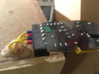
Could be the light bulb (for tweeter protection?) playing up, check to make sure its screwed in tight and also check to see if it has low resistance.
cheers
cheers
Maybe check the resistors, have had some run warm in similar arrangements.
Those are film capacitors, should last a lifetime, would be the last thing I would suspect.
I’ve seen the electrolytic type test with elevated values after years of use in filter circuits however.
Those are film capacitors, should last a lifetime, would be the last thing I would suspect.
I’ve seen the electrolytic type test with elevated values after years of use in filter circuits however.
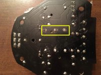
Usually turns out to be the solder joint where a screw bears down into a connection.
I think the torque breaks the copper foil around the solder joint, it can be hard to see unless you remove the solder.
Scrape some solder mask off around the pad, tin and solder on a wire link twisted around the pin.
I think the torque breaks the copper foil around the solder joint, it can be hard to see unless you remove the solder.
Scrape some solder mask off around the pad, tin and solder on a wire link twisted around the pin.
Attachments
Could be the light bulb (for tweeter protection?) playing up, check to make sure its screwed in tight and also check to see if it has low resistance.
cheers
ok thanks... what resistance range am i looking for?
Ok.. so most likely a solder connection unless it happens to be the light blub. Sounds tedious so I'll have to carve out some time for it. thanks everyone! If i have success I'll post an update.
- Home
- General Interest
- Car Audio
- Passive Crossover repair help needed