I have a z_amp that stopped working. After taking it apart and doing some research. Appeared one of the 2SB817 outputs are shorted.
I pulled all the outputs and also found a 2SD1047 on the opposite channel that is testing poorly too.
Questions:
1) Can I substitute 2SC5200N/2SA1943N - since I have them on hand (3 at least)? Do I need to change them all 2-of each PNP/NPN? I only have 2-NPN's and 1-PNP on hand. Trying to avoid an order - but not a big deal, they are at DK.
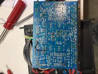
2) In the picture below, there are some wires and a resistor soldered on the bottom of the PCB. Doesn't really look "factory" but I'm unsure since I bought this 2nd-hand a while back.
Pics attached - A schematic (V3 I have V1, but similar), datasheets for the original 2SD1047 and possible substitute 2SC5200N and a picture of the bottom of the PCB
Any insight assistance would be appreciated.
Thanks,
Paul
I pulled all the outputs and also found a 2SD1047 on the opposite channel that is testing poorly too.
Questions:
1) Can I substitute 2SC5200N/2SA1943N - since I have them on hand (3 at least)? Do I need to change them all 2-of each PNP/NPN? I only have 2-NPN's and 1-PNP on hand. Trying to avoid an order - but not a big deal, they are at DK.
2) In the picture below, there are some wires and a resistor soldered on the bottom of the PCB. Doesn't really look "factory" but I'm unsure since I bought this 2nd-hand a while back.
Pics attached - A schematic (V3 I have V1, but similar), datasheets for the original 2SD1047 and possible substitute 2SC5200N and a picture of the bottom of the PCB
Any insight assistance would be appreciated.
Thanks,
Paul
Attachments
This amp has feedback, so output transistor substitutions should not be a big deal. As long as you go up in capability, not down.
The rails use 50v rated caps, so I'd assume Vceo of 2sc5200/2sa1943 is adequate. Usually later transistors have more max current capability and soa, I'll let you look at the datasheets to compare those numbers.
Usually for less distortion and better matching of load between transistors, one replaces ALL output transistors at once, with ones from the same vendor and and batch.
This appears to be a single output transistor pair so matching should be easier. But I would change the bottom transistor to one from the same decade production , anyway.
Matching can be made easier by changing the emitter resistor on the output transistor from .22 ohm to .47 or .51 ohm. This cuts output power a smidge. More important, the VI limiter Q213/214 becomes more sensitive, I'd increase r225/226 proportionately to keep the VI limiter from cutting on too early. More modern, you could remove r225/226 entirely and put on an external DC detection & speaker current limiting board (with relays or nfets) which prevents OT blowup with much less bad sound than a VI limiter.
Don't forget new mica washer & heat grease. Life mica is about 50 years.
Last edited:
Thanks for the info.
I bought a lot of 2SC3519A/2SA1386A (8 pairs) for my NAD rebuild and only used 4 pairs.
The biggest difference - other than higher voltage and current capacity (good things, as you said) is the frequency transistion.
OEM is 20MHz, the 2SC5200 is 30MHz and the 2SC3519A I just mentioned are 50MHz.
Is any of that a problem? Seems like everything else is very close or higher rated.
20-30 mhz shouldn't cause problem. those of us that fool with 1965 design equipment have to deal with the difference between 400 khz transistors and 2 mhz parts, which causes problems.
I find my amp with 4 mhz OT's sounds really great on high frequency sources, and noticebly better than the 400 khz parts (which got bad reviews versus vacuum tubes in 1966).
If you do get oscillation out (ac voltage with input signal shorted) put 10 ohm base stopper resistors in the base lines of the output transistors. Between driver & output base. I used carbon comp 2 watters since I had a dozen of them, don't know if inductance of modern metal film or wire wound resistors is a problem.
Last edited:
well - didn't go as smoothly as I planned.
Changed out all the outputs transistors (2-pair) to 3519A/1386A versions.
NOt sure if it's oscillating or what - but I have rail voltage on the right-channel speakers outputs and the left channel moves around quite a bit and pretty high at 100-240mV.
Checked the other small signal transistors - on the board, and they all check out okay with the Fluke.
Next step will be to start taking some voltages - I know the PSU, diode bridge and +/-15vDC and 12vDC regulators are working. I also checked the opamps and they are getting 15/12vDC.
DC out channel probably means a bad solder joint or shorted mica washer or something.
Why I usually do one channel or at most 2 parts at a time between tests. My work is not pluperfect, just I'm persistent and find my errors eventually. As my near eyesight gets less and less defined, the error rate has been going up.
I'd expect OT idle current to be off, with different age/capability output transistors. Fool with the voltage separater stack on the drivers as appropriate. DC speaker voltage wandering around means something in the dc part of the feedback circuit is not working right. That might be pre-existing symptom, why the amp blew the output transistor in the first place.
Last edited:
Question-
I tested the 3 op-amps on the board and I’m confused
JRC 2072D - data sheet says max of 6Vdc but I’m getting 12v on pin 8?
JRC4558DD in the middle has +15 on pin 8 and -15 on pin 4
Other JRC4558DD only has 12Vdc on pin 8, no voltage on pin 4?
Strange these have different voltages and not similar, either only + or both having -/+?
Am I crazy, or just using them for different purposes?
U301 4558 clearly has +12 & 0 as power pins, up near the top. Weird but acceptable with e-caps in and out. The voltage on the inputs just has to be not too close to the power voltages, see the chart maximum peak output voltage versus supply voltage.
U101 TL072 clearly has +-15 on power pins. 8 is plus, 4 is minus.
TL072 is capable of much better than 6 v power on pin 8, +-18 max on the TI datasheet I've got. jrc2072 may have been a substandard copy at some time but I'm sure if they continued to sell them they got the voltage capability up to TI standards.
Use IC# when talking about IC's please. They are on the schematic.
BTW wandering DC out on speaker channel can be voltage leakage through flux around component in the feedback chain like R217. Could also be leakage through faulty C206 or C207 or C108. Or flux leakage around R219 or R230. Or flux under the IC socket U101. You wash flux off with 70% isoprophyl alcohol and a Q-tip or something.
Last edited:
- Status
- Not open for further replies.
- Home
- Amplifiers
- Solid State
- Parasound Z-Amp replacement transistors