I have an older Parasound HCA-1000A power amp that has developed an issue where it's red LED "Standby" light is on all the time now but I'm still getting sound. The amp was modified years ago but never exhibited this issue until recently. Typically, when working correctly, when powered up the amp displays the red standby for a few moments while the relays are working and then you can hear a click and the red light goes out and the green LED "Normal" indicator comes on. Here's the weird thing. I noticed that when I disconnect my interconnect from the amp to my preamp the amp does not display the red LED standby light, it actually goes green and I hear the relay click. So, when the amp and preamp are connected with an interconnect I get the red LED Standby light (though I still get sound). It doesn't matter if preamp itself is on or off by the way, it exhibits the issue. I did try another interconnect just in case by the way, made no difference.
Here's a snippet from the Parasound owner's manual:
-------
The Standby LED will also light whenever there is a short circuit or other fault that triggers the protection circuitry. This may indicate that excess DC is present at the amplifier's input, a speaker impedance overload, a short circuited speaker line, or possible internal fault. If this LED remains lit, remove power to the amplifier and check all connections. During this time, the protection circuits should automatically reset.
-------
Once again, never had this issue with this amp over the years until recently, suddenly out of the blue. Seems to be related to the RCA inputs and my preamp's output. Since nothing has really changed in my setup is it possible that perhaps it's a relay or maybe even a cap associated with/near a relay is out of spec and and throwing the red LED? Odd thing is I still get sound, the amp's output is not muted in protection mode. I do not get a huge thump when I turn this amp on by the way. Any help would be appreciated, thanks!
Last edited:
......there is a thread
Parasound HCA 1000A Overload Indicator
......can you measure the offset voltage at the output of the amp ?
Parasound HCA 1000A Overload Indicator
......can you measure the offset voltage at the output of the amp ?
Thanks, mjf, I appreciate your reply. I actually did see that post in my research but they are describing an issue with the overload LED's illuminating and I'm not having that issue. The overload indicators on my amp have not illuminated and are separate LED's from the AC Line LED (amber color), Standby LED (red color) and the Normal LED (green). In my case the Standby red LED stays illuminated. The red LED typically illuminates when the unit is powering up for a few seconds before it turns off (relays) and the green LED glows to indicate Normal but the red stays illuminated, yet I still get sound. According to that snippet from the manual the amp is indicating fault of some sort and is staying in protection/Standby mode yet I still get sound, which seems odd.
The manual is right. HCA1000A is a DC coupled power amp. It does have DC servo circuit capable of nulling the input DC offset, but only to a certain level. Beyond that level, the standby LED would light up. Further beyond and the speaker relay would disengage to protect the speakers.
First keep the pre-amp connected and sweep the volume knobs in the back of the amp between all the way up and all the way down and see if that would make difference to the stand-by indicator. Doing that would confirm/rule-out DC offset at the input, in other words a faulty pre-amp. If you have a multimeter, measure between the speaker terminals for DC voltage. Should read within a few mV.
If that doesn't fly the next best place to dig would be the speaker protection relay circuit. The relay is driven by the compound transistor(Q005/Q006). When the compound transistor turns hard on (normal operation mode) it shunts the cold side of relay coil to GND to close the relay driving circuit, and by doing that, it also turns off the stand-by LED.
When somehow the compound transistor turns on but not quite hard on, you'd get a illuminated stand-by LED AND a speaker relay that remains engaged. A marginal DC offset at the amp output could do that, a half-way faulty/degraded capacitor C022 could do that too.
Attachments

Thanks, nattawa for your reply, I really appreciate it. This amp was modified about 10 years ago by a guy named Steve Sank and it's worked flawlessly since. The mod included removing the volume pots, loop out and bridge mode/switch, so it's now just a standard power amp. So I will try measuring between the speaker terminals for DC voltage.
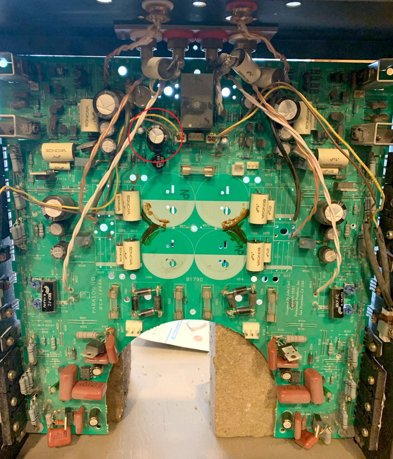
In regard to your second thought, Attached is a photo of this amp taken when I was replacing the four large 63v/10,000uf filter caps earlier this year. I don't have the amp open at the moment, but I believe the cap circled in red is CO22, isn't it? Are you able to tell by referring to the schematic?
Thanks!
Last edited:
There are two capacitors in that red circle, a big black shiny one in the middle and a small blueish dusty one to the north-west-west. The small blueish dusty one appears to be C022. And yes, do take a DC voltage reading at output, with and without the preamp interconnected.
There is another possible cause for a DC offset at the input from the mod that took out the volume pots. Without those pots the DC resistance at the input became 1M-ohm vs prior 47K-ohm, making the amp more susceptible to a leaky output capacitor in a preamp.
I really appreciate you taking the time to help. I pulled the amp and opened it up and verified that CO22 is in fact the little blueish cap.
Regarding the removal of the pots, it's odd that at one point I wasn't getting the red LED with this preamp, but I see what you mean. If there is a leaky output cap in the preamp would swapping out the C022 potentially help this? Sorry, I'm a bit of a newb here. I love DIY and am trying to get more into it and still learning, have to start somewhere.
I've been meaning to get a digital multimeter as I only have an analog one right now and not sure if that would work measuring the outputs? Sorry for the total newb-ness here but how do I do that measurement? First, is the amp supposed to be on when I do this? With and without the preamp connected, I'll do that. Do I have the positive lead of the meter on the positive binding post and the negative lead on the negative lead of the negative binding post? Thanks!
C022 is one of the plausible causes independent of DC offset at the amp output, but given the known conditions of the amp as far it seems a lot less likely to be the problem. To answer your question, no, C022 will not fix the DC offset. C022 is part of the power loss detection circuit that serves to quickly disengage the speaker relay before the main power supply rails collapse, by the way.
Analog meter is ok for the job, just be mindful of using a proper range and starting with a broader range first, say 10V, to ID the polarity. The DC offset can be either positive or negative, simply reverse the probes when the pointer hand in the meter goes the wrong way. I'd expect to see an offset about a few hundred mV, so the 1V range should be good for an accurate reading.
You'd want to probe it when the power is on to both the preamp and the amp, with the power amp being warmed up, with preamp disconnected from the amp, meter range to 10V, probe to ID polarity, range to 1V, probe for accurate reading, write down the offset reading, repeat polarity ID and offset value reading on the other channel, remove the meter, turn off the power to the amp, reconnect the interconnect to the preamp, turn power back on to the amp, repeat polarity ID and offset reading.
- Home
- Amplifiers
- Solid State
- Parasound HCA-1000A Fault Indicator Red Light