Hello 🙂
I am designing my first tube amp. Before I start assembling, I'd like to get approval or advices from more experienced constructors 🙂
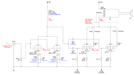
The project is a simple, two-stage parallel single ended, based on the e88cc/6922 and 2 x KT150 tubes per channel.
The amplifier is designed for the triode mode, although the ultralinear option is also provided.
Low THD was not the goal of the project. I care about a favorable ratio of even to odd harmonics and a warm, saturated tube sound. The LTSpice simulation shows just over 5% of the second and 0.2% of the third harmonics at full power. Of course, in real life, the results may be different than simulated 🙂
Less parts
No grid stoppers for the driver tubes - the volume pot will fulfill this role(?)
No grid stoppers for the power tubes
No coupling capacitor at the input - I assume that the capacitor is at the output of the source (DAC)
Cathode bypass capacitors for the driver: Nichicon FG. The Nichicon KZ is positioned higher, but its sound is supposedly less warm.
Elna Silimic might have been better, but nowadays it's probably hard to get a better version (ARS, AXF) than the standard RFS.
Driver anode choke:
Lundahl LL1668-15mA (Coils in Series, DC Resistance 680Ω, x 235V~ 100Hz Ripple, 15mA 167H)
The choke is designed for 15mA, but according to the website
http://jacmusic.com/lundahl/applications/How-to-bias-the-LL1667-LL1668.pdf
...DC current can be exceeded if the AC signal voltage is lower.
LL1667-15mA (Coils in Series, DC Resistance 2400Ω, x 390V~ 100Hz Ripple, 15mA 270H) has a higher inductance, but the forums say that 1668 sounds better than 1667.
The output transformer has 1500 ohm impedance, so each of the two power tubes sees a little over 3000 ohm (the screen current must also pass through the transformer's winding and it seems to raise the impedance)
I am also considering a transformer with an alternative lower impedance tap to achieve more power.
PSU is a very important part of every amplifier - in order not to make a mess in this thread, I will present the PSU circuit (as well as a fixed bias circuit for power tubes) in another thread, when I get approval for this project.
So...
Thanks in advance for any suggestions or comments!
Rafal
I am designing my first tube amp. Before I start assembling, I'd like to get approval or advices from more experienced constructors 🙂
The project is a simple, two-stage parallel single ended, based on the e88cc/6922 and 2 x KT150 tubes per channel.
The amplifier is designed for the triode mode, although the ultralinear option is also provided.
Low THD was not the goal of the project. I care about a favorable ratio of even to odd harmonics and a warm, saturated tube sound. The LTSpice simulation shows just over 5% of the second and 0.2% of the third harmonics at full power. Of course, in real life, the results may be different than simulated 🙂
Less parts
No grid stoppers for the driver tubes - the volume pot will fulfill this role(?)
No grid stoppers for the power tubes
No coupling capacitor at the input - I assume that the capacitor is at the output of the source (DAC)
Cathode bypass capacitors for the driver: Nichicon FG. The Nichicon KZ is positioned higher, but its sound is supposedly less warm.
Elna Silimic might have been better, but nowadays it's probably hard to get a better version (ARS, AXF) than the standard RFS.
Driver anode choke:
Lundahl LL1668-15mA (Coils in Series, DC Resistance 680Ω, x 235V~ 100Hz Ripple, 15mA 167H)
The choke is designed for 15mA, but according to the website
http://jacmusic.com/lundahl/applications/How-to-bias-the-LL1667-LL1668.pdf
...DC current can be exceeded if the AC signal voltage is lower.
LL1667-15mA (Coils in Series, DC Resistance 2400Ω, x 390V~ 100Hz Ripple, 15mA 270H) has a higher inductance, but the forums say that 1668 sounds better than 1667.
The output transformer has 1500 ohm impedance, so each of the two power tubes sees a little over 3000 ohm (the screen current must also pass through the transformer's winding and it seems to raise the impedance)
I am also considering a transformer with an alternative lower impedance tap to achieve more power.
PSU is a very important part of every amplifier - in order not to make a mess in this thread, I will present the PSU circuit (as well as a fixed bias circuit for power tubes) in another thread, when I get approval for this project.
So...
- Won't it explode? 😉
- Does the presented circuit make sense?
- Is there a chance that the construction will sound decently?
- Did I forget something?
Thanks in advance for any suggestions or comments!
Rafal
Attachments
1. The E88CC is an RF tube, fully capable of oscillating at hundreds of MegaHertz in a circuit that has parasitic L and parasitic C (all circuits have those parasitics).
The plates are in parallel; the grids are in parallel, the cathodes are in parallel (well, they are only separated by the capacitive reactance [and the lead inductances] of the bypass caps.
So, no ECC88 grid stoppers, why not?
2. You only need the high resistance of a 100k potentiometer if you have a tube preamp that has high output impedance, or if you have a weak signal source or weak solid state preamp.
If the preamp or signal source is very low impedance, and the volume is set to - 6dB, then the two grids "see" a driving impedance of 50k Ohms (it is higher than 50k, if the signal source has medium or high impedance output.
The two Miller effects of the high gain parallel E88CC, with 50k Ohms driving it will probably be about -1dB at 10kHz, and -3dB at 20kHz (just an estimate, you can look up the grid to plate capacitance, multiply times 2, and multiply that times the grid to plate gain.)
Solve for the -3 dB frequency (f), where f = 1 / (50k x 2 x pi x C), where C is the two Miller Effect capacitances in paralell.
Suppose grid to plate is 1.5 pF, and gain is 33, one triode Miller Effect is 49.5pF, so 2 x that is 99pF then . . .
1 / (50k x 2 x pi x 99x10^-12 F
F, -3dB = 32kHz This is a single pole, so it is -1dB @ 16kHz.
You may not care, but if the output transformer is also -1dB @ 16kHz, the amp will be -2dB @ 16kHz.
3. The full primary of the output transformer may not be -1dB @ 16kHz, but if there is leakage inductance from the primary plate windings at the plate connection, to the primary screen windings, the plate and screen will be slightly out of phase, so Ultra Linear mode might have a different high frequency rolloff than Triode mode.
4. Go to the KT150 data sheet plate curves in Triode Mode, and solve the curves for plate impedance, rp.
Then Go to the KT150 data sheet plate curves in Ultra Linear Mode (at the UL tap % of your output transformer), and solve the curves for plate impedance, rp.
As you said, each tube sees 3000 Ohm load (parallel operation on 1500 Ohm primary)
Suppose triode mode rp = 1k. Then 3000/1000 = 3. The damping factor will be about 3 (a little less than 3, because of the primary windings DCR and the secondary windings DCR).
5. Using the 15mA rated choke at 17.4mA may cause low frequency saturation.
And check, is the 15mA rating for Series connection, or for Parallel connection?
6. Caution: Never change the switch position of the triode / ultra linear switch when the amplifier is on.
That can hurt your tweeters, ears, and perhaps the output transformer.
Have fun building and listening!
Last edited:

Thank you very much for expert advices 🙂
I have analyzed this point and I get different results :/ (see the picture below...)
High frequency response (-3dB) formula for low pass filter is: f = 1 / (2 * PI * R *C)
But... R is like a parallel combination of the volume pot voltage divider resistors, so:
R = R1 || R2
R = 50 kOhm || 50 kOhm
R = 25 kOhm
Both the simulation in LTSpice and the calculation shows the result:
-1dB @ 32kHz
-3dB @ 64kHz
Did i miss something? :/

It's not an impressive value...I will investigate the topic... :/
I have the Ayon Amp with triode/pentode switch, I switch it when it's off 🙂
Doesn't the volume pot resistor near the triodes act as a grid stopper? Is it too far?
Thank you, I still have a lot to learn! 😀
2. You only need the high resistance of a 100k potentiometer if you have a tube preamp that has high output impedance, or if you have a weak signal source or weak solid state preamp.
If the preamp or signal source is very low impedance, and the volume is set to - 6dB, then the two grids "see" a driving impedance of 50k Ohms (it is higher than 50k, if the signal source has medium or high impedance output.
The two Miller effects of the high gain parallel E88CC, with 50k Ohms driving it will probably be about -1dB at 10kHz, and -3dB at 20kHz (just an estimate, you can look up the grid to plate capacitance, multiply times 2, and multiply that times the grid to plate gain.)
Solve for the -3 dB frequency (f), where f = 1 / (50k x 2 x pi x C), where C is the two Miller Effect capacitances in paralell.
Suppose grid to plate is 1.5 pF, and gain is 33, one triode Miller Effect is 49.5pF, so 2 x that is 99pF then . . .
1 / (50k x 2 x pi x 99x10^-12 F
F, -3dB = 32kHz This is a single pole, so it is -1dB @ 16kHz.
You may not care, but if the output transformer is also -1dB @ 16kHz, the amp will be -2dB @ 16kHz.
I have analyzed this point and I get different results :/ (see the picture below...)
- I assume that the source impedance is low (~100 Ohms), which I will ignore in further calculations
- I assume one triode Miller effect is 49.5pF
- I set the volume pot to -6dB, dividing 100 kOhms into 50 kOhms and 50 kOhms
High frequency response (-3dB) formula for low pass filter is: f = 1 / (2 * PI * R *C)
But... R is like a parallel combination of the volume pot voltage divider resistors, so:
R = R1 || R2
R = 50 kOhm || 50 kOhm
R = 25 kOhm
Both the simulation in LTSpice and the calculation shows the result:
-1dB @ 32kHz
-3dB @ 64kHz
Did i miss something? :/
It's hard to find information, but for example, for the LL1667 / 15mA choke (probably for windings in series):5. Using the 15mA rated choke at 17.4mA may cause low frequency saturation.
And check, is the 15mA rating for Series connection, or for Parallel connection?
- Standing DC current: 15mA,
- Saturating current: 25mA
- Max DC current per winding, all applications: 40 mA
The damping factor will be about 3 (a little less than 3, because of the primary windings DCR and the secondary windings DCR).
It's not an impressive value...I will investigate the topic... :/
6. Caution: Never change the switch position of the triode / ultra linear switch when the amplifier is on.
That can hurt your tweeters, ears, and perhaps the output transformer.
I have the Ayon Amp with triode/pentode switch, I switch it when it's off 🙂
The E88CC is an RF tube, fully capable of oscillating at hundreds of MegaHertz in a circuit that has parasitic L and parasitic C (all circuits have those parasitics).
The plates are in parallel; the grids are in parallel, the cathodes are in parallel (well, they are only separated by the capacitive reactance [and the lead inductances] of the bypass caps.
So, no ECC88 grid stoppers, why not?
Doesn't the volume pot resistor near the triodes act as a grid stopper? Is it too far?
Have fun building and listening!
Thank you, I still have a lot to learn! 😀
Ideally, the grid stopper should be as close to the tube as possible. Tie them to the tube socket is common practice. The volume pot is not a substitute for an actual grid stopper resistor. Use a high quality volume pot because if the wiper lifts off the conductive element you will have problems as your tube is no longer referenced to ground! You can always put a 1 Meg resistor in parallel with the pot as cheap insurance.
tuberabbit,
Correct. 25k driving the Parallel E88CC Grids. (I mistakenly said 50K).
Parallel connection of two E88CC RF triodes:
You have an RF path from one cathode, to a wire, to a capacitor, to a ground wire, to another capacitor, to the 2nd cathode.
Keep the wiring short, all of that wiring and capacitors is an RF inductor.
You have a wire from one grid to the other grid. Keep it short, it is an RF inductor.
You have a wire from one plate to the other plate. Keep it short, it is an RF inductor.
Each of the grids, cathodes, and plates have capacitance to each other (Which is why some of those dual triodes have a shield between the triodes).
But in each triode, all 3 elements have capacitance to each other.
Parasitic inductance and parasitic capacitance sometimes makes an otherwise simple tube circuit oscillate.
I study various forms of RF oscillators, including the Butler oscillator, and the Colpitts oscillator.
Your parallel E88CC might just want to oscillate.
I used a 12AY7 in parallel, each cathode had its own bias resistor and bypass capacitor, each grid had its own grid stopper, and the plates were tied together.
It oscillated.
Even though each grid had its own individual grid stopper, I had to put a 1k resistor from each plate, and connect the other end of the 1k resistors together to the plate load.
That fixed the problem.
your mileage may vary
Thank you for the very detailed explanation.
So, I'll put the grid stoppers, as close as possible to the socket pins of the tubes and use a high quality volume pot.
So, I'll put the grid stoppers, as close as possible to the socket pins of the tubes and use a high quality volume pot.
- Home
- Amplifiers
- Tubes / Valves
- Paraller SE E88CC/KT150 tube amp design