tried this circuit with master/slave config and sounds good, i can definitely hear improvements. now i'm wondering if it would be sensible to add another 'slave' to it, another unity gain module, input fed from the output of the 1st 'slave' and all the outputs combined once more before the feedback resistor.
what do you think?
and is slave/master config better than composite method?
https://e2e.ti.com/blogs_/archives/b/thesignal/archive/2013/03/26/paralleling-op-amps-is-it-possible
what do you think?
and is slave/master config better than composite method?
https://e2e.ti.com/blogs_/archives/b/thesignal/archive/2013/03/26/paralleling-op-amps-is-it-possible
would be sensible to add another 'slave' to it, another unity gain module, input fed
from the output of the 1st 'slave' and all the outputs combined once more before the feedback resistor.
Yes, each op amp with a series resistor on its output.
I think you can get better results with a composite using an opamp feeding a high current Buffer.
The lme49600 datasheet shows excellent performance. I built a low gain headphone amplifier like that.
The lme49600 datasheet shows excellent performance. I built a low gain headphone amplifier like that.
Last edited:
Oh, the power of wishful thinking/placebo effect 🙂and sounds good, i can definitely hear improvements.
Funny thing is not even Bruce Trump, the article's writer claims that, only that: parallel two op amps to get twice the output current? , period.
Will that "sound better"?
Only if you expect it. 🙂
Only place where it would make any difference is when driving a very low impedance load, needing more current than what a regular Op Amp can supply, two real world cases being a reverb tank driver or a headphone output , where actually an Op Amp is a poor choice to begin with and a way higher current capability buffer, either discrete or integrated is the real solution, as suggested by Andrew T .
In any other case, driving any reasonable load, no difference will be heard, why should any exist?
Practical example: a TL072 can readily supply up to around 5mA or fully drive a 2k load (just look at the datasheet) ... two of them in parallel can supply 10 mA ; 3 will offer 15mA and so on.
Only case I can see it justified (besides the two electromagnetic loads I mentioned) is a preamp which wants to fully drive a 600 ohms load ... but a better design choice is either to add a couple transistors, a current buffer IC, or plain use a higher current capability Op Amp such as NE5532 , which is designed to drive 600 ohms loads.
Oh, the power of wishful thinking/placebo effect 🙂
Noise will be lower. It wrote on Douglas Self's book. He really measured it.
The difference is there and whether I find it to be an improvement or not is subjective- so why take the fun out of it?
Did he hear the lower measured noise?
Please ask Douglas Self 😀 He did not write on his book if he can hear the different.
Please ask, if you do not able to hear, or you can simple try it your self.
The difference is there and whether I find it to be an improvement or not is subjective- so why take the fun out of it?
I notice a difference too on changing the loading of an opamp - these days I prefer feedback networks in the 100's of kohms to minimize the reduction in dynamics that occurs.
You might get a similar improvement from just a single opamp but with the output biassed into classA with a CCS to the -ve rail.
The OP never said what Opamp he's using nor load range and if CL resistor, so IMO anything is possible.
There's usually duals in a single package, anything more than that is a tradeoff to stepping up to a new topology (see links in the article). Study the data sheet, most generic opamps are becoming unhappy Rl < 2K. TI /BB has audio opamps designed for high current headphones.
Keep input gain setting resistance and feedback from becoming too large to add Opamp input current noise sources from impacting the system noise floor. many LinearTech App notes on doing this. don't forget input offsets can eat into output current delivery on paralleling stages.
Last edited:
The difference is there and whether I find it to be an improvement or not is subjective- so why take the fun out of it?
I think current is an issue with opamps, hence, I'm not surprised if it is audible 🙂 In fact, too many issue with opamps...
I notice a difference too on changing the loading of an opamp - these days I prefer feedback networks in the 100's of kohms to minimize the reduction in dynamics that occurs.
You might get a similar improvement from just a single opamp but with the output biassed into classA with a CCS to the -ve rail.
I too have been messing with feedvback values all weekend. My setuo is (breadboard of course)
Salas ccs>mosfet.gyrator> tl081 master/ne5532 slave
Gain is set for 2. I can definitely hear tightening of the sound, deeper bass with higher value resistors but after a point the sound gets too 'thin' (hifi?) For my liking. If.more.current thru the feedback means woolier bass, then so be it. Ive happily settled at 500ohm at the moment 😱
Psu additions were.the biggest improvements, not surprisingly.
Im choosing faster opamps for slave duty so it does not fight.the master 😛
Im wonderding if i should put ccs after the gyrator instead. The gyrator is this circuit and ccs taken straight from the salas lv shunt.
Grundlagen, Einführung, Berechnung, Theorie,Platine Bausatz, Bauplan Schaltplan Mosfet Gyrator
Grundlagen, Einführung, Berechnung, Theorie,Platine Bausatz, Bauplan Schaltplan Mosfet Gyrator
Given that you want a low source Z output voltage, gyrator first makes more sense to me. A gyrator simulates a big inductor, so that gives an LC lowpass response, and a resonance peak is about the last thing you want in your impedance response.
So is this a single supply design, almost sounds like it? In this case I hope you have avoided some of the usual pitfalls of virtual grounds, like accidentally wrecking PSRR and other such fun stuff. Always generate VGND with an R-RC, never RC-RC.
You'll run into trouble with very high feedback network R values (read 10s of kOhms and up) because of op-amp input capacitance (~6 pF for TL07x and similar, changing somewhat with common-mode input voltage), resulting in high-frequency response peaking and possibly even oscillation. A small capacitor across the feedback resistor should sort this out; its value should be at least about Cin,OP * Rg/Rf. Since in audio we are not interested in super-high bandwidth anyway, it can also be bigger, so if you've got anything in the 10p-47p range floating around, try this.
In a circuit like that, I might use something like Rf=Rg = 1k..3k3. There's not an awful lot of a point going too low as a TL081 isn't exactly low-noise. These were originally intended for (old-style) inverting circuits using 10k-22k resistor values, hence why neither load driving nor common-mode performance were considered too important. You could actually try one like this, too, as buffer operation is independent.
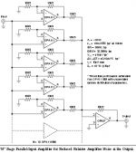
Note that while the schematic in the original article gives equal current sharing resistor values (R3, R4), they should be chosen differently when combining different op-amp types, depending on their current capability. Here I'd say maybe 220-470 ohms for the TL081 plus 47 ohms for the NE5532. An additional 10-47 ohms between output and load is recommended.
NE5532s at unity gain can be a bit finicky, so decent supply decoupling is much recommended.
From about a gain of 3 (noninverting) / 2 (inverting) up, you could also combine two opamps of the same type.
So is this a single supply design, almost sounds like it? In this case I hope you have avoided some of the usual pitfalls of virtual grounds, like accidentally wrecking PSRR and other such fun stuff. Always generate VGND with an R-RC, never RC-RC.
You'll run into trouble with very high feedback network R values (read 10s of kOhms and up) because of op-amp input capacitance (~6 pF for TL07x and similar, changing somewhat with common-mode input voltage), resulting in high-frequency response peaking and possibly even oscillation. A small capacitor across the feedback resistor should sort this out; its value should be at least about Cin,OP * Rg/Rf. Since in audio we are not interested in super-high bandwidth anyway, it can also be bigger, so if you've got anything in the 10p-47p range floating around, try this.
In a circuit like that, I might use something like Rf=Rg = 1k..3k3. There's not an awful lot of a point going too low as a TL081 isn't exactly low-noise. These were originally intended for (old-style) inverting circuits using 10k-22k resistor values, hence why neither load driving nor common-mode performance were considered too important. You could actually try one like this, too, as buffer operation is independent.
Note that while the schematic in the original article gives equal current sharing resistor values (R3, R4), they should be chosen differently when combining different op-amp types, depending on their current capability. Here I'd say maybe 220-470 ohms for the TL081 plus 47 ohms for the NE5532. An additional 10-47 ohms between output and load is recommended.
NE5532s at unity gain can be a bit finicky, so decent supply decoupling is much recommended.
From about a gain of 3 (noninverting) / 2 (inverting) up, you could also combine two opamps of the same type.
Last edited:
We've been using stacked I/V AD844 opamps with great success, to lower input impedance as seen by the current output dac, to raise the current limiting headroom, and give less distortion, if the output buffer of the AD844 was used we only needed 100ohm series output isolating resistors.
But these are used without global feedback, so I don't know what happens when feedback is applied.
http://www.diyaudio.com/forums/digital-source/227677-using-ad844-i-v.html
Cheers George
But these are used without global feedback, so I don't know what happens when feedback is applied.
http://www.diyaudio.com/forums/digital-source/227677-using-ad844-i-v.html
Cheers George
Last edited:
- Status
- Not open for further replies.
- Home
- Source & Line
- Analog Line Level
- parallel opamp?