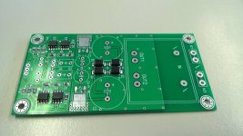
Currently i'm building my latest headphone amplifier.
It uses 2 dual opamps per side. 1 opamp channel for voltage amplification and 3 opamp channels as buffer in parallel. Global feedback is used.
Very small, only 50x100mm including mains powersupply.
It is my first design with SMD components. First test are good. Very quiet, and more then enough drive for low impedance headphone.
Attachments

You should better use a buffer ic like BB BUF634 or LME49990.
As input ic you should a modern BJT or DIFET OPAMP.
As input ic you should a modern BJT or DIFET OPAMP.
Last edited:
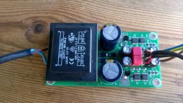
Could do that, but as this was my first ever SMD layout i decided to use cheap commonly available parts. PCB including all components is only around 15 Euro 🙂
You should better use a buffer ic like BB BUF634 or LME49990.
As input ic you should a modern BJT or DIFET OPAMP.
Neat looking PCB. Mooly did a test recently comparing arrays of 5 different opamps. It was virtually impossible to hear any differences at all, and those who said they did had preferences all over the map. The one thing it proved is that preconceived notions are stronger than reality. In other words, your choice for ne5532 is an excellent one.
Thanks, I'm very pleased with the result untill now. Sounds great. Just waiting for the SMD voltage regulators. I temporarily used TO-92 parts to test the board.
Neat looking PCB. Mooly did a test recently comparing arrays of 5 different opamps. It was virtually impossible to hear any differences at all, and those who said they did had preferences all over the map. The one thing it proved is that preconceived notions are stronger than reality. In other words, your choice for ne5532 is an excellent one.
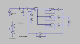
That low? Doesn't this give too much imbalance between the parallel opamps?
Btw, I see you use 100Ohm resistors after the paralleled opamps. 1 Ohm might be better.
That low? Doesn't this give too much imbalance between the parallel opamps?
I agree that 100 Ohms here is excessive and will result in needlessly wasted output current capability. The determining factors for output balancing resistors is the maximum output offset voltage differential divided by output current. The 5532 has a maximum input offset voltage of 5mV (worst case) and a maximum output current of 60mA (short circuit.) Since the output buffers are unity gain, maximum output differential between them is 10mV. So doing the math, 10mV divided by 60mA gives 17 mOhms. Using the "rule of ten" the balancing resistors should be at least 1.7 Ohms, but any value up to around 10 Ohms should work just fine.
Mike
Last edited:
Btw, I see you use 100Ohm resistors after the paralleled opamps.
1 Ohm might be better.
Hi,
No. 1R is pretty pointless. 10R is a reasonable minimum.
rgds, sreten.
Last edited:
Well Douglas Self used 1 ohm with 32 NE5532 parallel...
https://guitar-gear.ru/forum/index.php?app=core&module=attach§ion=attach&attach_id=37677
https://guitar-gear.ru/forum/index.php?app=core&module=attach§ion=attach&attach_id=37677
What Mike says makes sense, but I think anything from 1 Ohm upwards will be ok. 10 Ohms is already excessive. The reason to aim for as low as possible series resistors is that headphones are designed for voltage drive, so the lower the output impedance, the better they will follow the manufacturers intention.
What Mike says makes sense, but I think anything from 1 Ohm upwards will be ok. 10 Ohms is already excessive. The reason to aim for as low as possible series resistors is that headphones are designed for voltage drive, so the lower the output impedance, the better they will follow the manufacturers intention.
The buffers and their associated balancing resistors are inside the feedback loop, so output impedance is not affected. Only real penalty for higher resistance(within a reasonable value, of coarse) is a SLIGHT reduction in maximum output voltage.
Mike
Sreten has a way of being wrong in an admirable fashion 🙂
Mike, they are outside the loop, please refer to the schematic.
Mike, they are outside the loop, please refer to the schematic.
Sreten has a way of being wrong in an admirable fashion 🙂
Mike, they are outside the loop, please refer to the schematic.
You might want to look at the schematic again, the output buffers and their associated balancing resistors ARE inside the GNFB loop.
Mike
What Mike says makes sense, but I think anything from 1 Ohm upwards will
be ok. 10 Ohms is already excessive. The reason to aim for as low as possible
series resistors is that headphones are designed for voltage drive, so the lower
the output impedance, the better they will follow the manufacturers intention.
Hi,
Output impedance is determined by the feedback loop.
What you don't want is excessive power loss into low
impedance phones. 3x10R at 3.3R will drive 8 ohm +.
The output impedance is not 3.3R, its far less.
rgds, sreten.

I've done similar exercise before, with 5532's and some other opamps too. If it will be any useful, here it is - http://www.diyaudio.com/forums/headphone-systems/270294-crocodile.html There are also a few spectra of the output signal.
Also have some alternative frequency compensation scheme which does not require output filter to decouple from cable capacitance and driver inductance.
Also have some alternative frequency compensation scheme which does not require output filter to decouple from cable capacitance and driver inductance.
Last edited:
- Status
- Not open for further replies.
- Home
- Amplifiers
- Headphone Systems
- parallel opamp amplifier