Some of you might be interested in my Paper and Glue SMD circuit construction technique (if I dare call it a technique):
Paper and Glue SMD Circuit Construction
I personally find it a useful alternative to having to make a PCB every time I want to do something with SMD components.
Paper and Glue SMD Circuit Construction
I personally find it a useful alternative to having to make a PCB every time I want to do something with SMD components.
Very clever tip! 🙂 I have never built dead bug style circuits with SMD before but may try it now. This will work for larger standard components too I think?
Thanks.
Thanks.
That's a very clever idea 🙂
I cant help wondering if we can take this further?
Sadly the author states that chips might not work this way. I'm not sure why? Most of the interesting new chips are SMD, so I would be curious if I can do more with less external fabricators for prototyping. This looks like a slow but effective technique.
Adding to this I have found cardboard with PVA wood glue and a skin of aluminium foil to be useful for prototype boxes and surprisingly strong.
I build lot of speaker enclosures out of paper faced foam core board with great success. I am thinking of applying SMD components to foam core boards as substrates (http://www.diyaudio.com/forums/full-range/223313-foam-core-board-speaker-enclosures.html) as it is stiff and keeps shape nicely and lets you make a box with the main board. I am about to start a new class-D amp project using the TPA3118D2 chip from TI which is only available as a 32 pin SMD. Aluminum glued to opposite side makes nice ground plane to reduce noise pickup.
My question is this: if I glue components to a stiff foam core board and then solder them, why remove from the paper board? Just leave them glued to board as nice mechanical substrate?
My question is this: if I glue components to a stiff foam core board and then solder them, why remove from the paper board? Just leave them glued to board as nice mechanical substrate?
Last edited:
If you are doing a class D design you would be better with a double sided PCB and a ground plane. This is what the auther was reffering to whan certain circuits or chips wont work this way. Digital real does require a ground plane to work correctly, especially with todays devices that have quite fast rise times.
 Fast modern digital devices require good ground planes and proper supply decoupling.. Note that you can use the dead bug approach on single or double sided pcb material if you need to quickly prototype something. Scrub the copper with scotchbrite or similar before starting in order to get good solder joints to the plane. A dremel with a small grinding bit offers even more possibilities.
Thanks for the feedback about digital circuits needing good ground planes. The digital aspects of the circuit reside within the confines of the IC and the output leads to the first choke filter. Maybe I can glue a foil ground plane underneath those sections? The rest is just audio frequencies. I want to glue it to foam core board as a matter of tradition for fun because the speakers are also made of foam core. I want to have an "all foam core audio system." 🙂
The circuit I am trying to build will resemble this (somewhat simplified to remove all the options with jumpers). http://www.ti.com/lit/ug/slou342/slou342.pdf
The circuit I am trying to build will resemble this (somewhat simplified to remove all the options with jumpers). http://www.ti.com/lit/ug/slou342/slou342.pdf
Here is a good explanation of why ground planes are good, not just for digital, low level analogue benefits from them to.
http://www.x2y.com/filters/TechDay0...log_Designs_Demand_GoodPCBLayouts _JohnWu.pdf
http://www.x2y.com/filters/TechDay0...log_Designs_Demand_GoodPCBLayouts _JohnWu.pdf
Bob Pease was an advocate of those deadbug prototypes. You can read more about it in his Troubleshooting Analog Circuits book.
I think the aluminum-backed foam board might work if the stuff is not too thick, so the parts and interconnections can be kept close to the ground plane. I don't see a reason why the paper needs to be removed.
I think the aluminum-backed foam board might work if the stuff is not too thick, so the parts and interconnections can be kept close to the ground plane. I don't see a reason why the paper needs to be removed.
I just wanted to give an update that I used the inspiration from this technique for my class D amp build with dead bug method. I glued it on foam core board with a foil ground plane, I did not remove from paper but just left it as substrate for a foam core amplifier.
http://www.diyaudio.com/forums/class-d/219730-tpa3118d2-6.html#post3413886
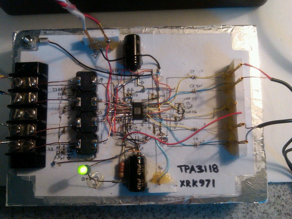
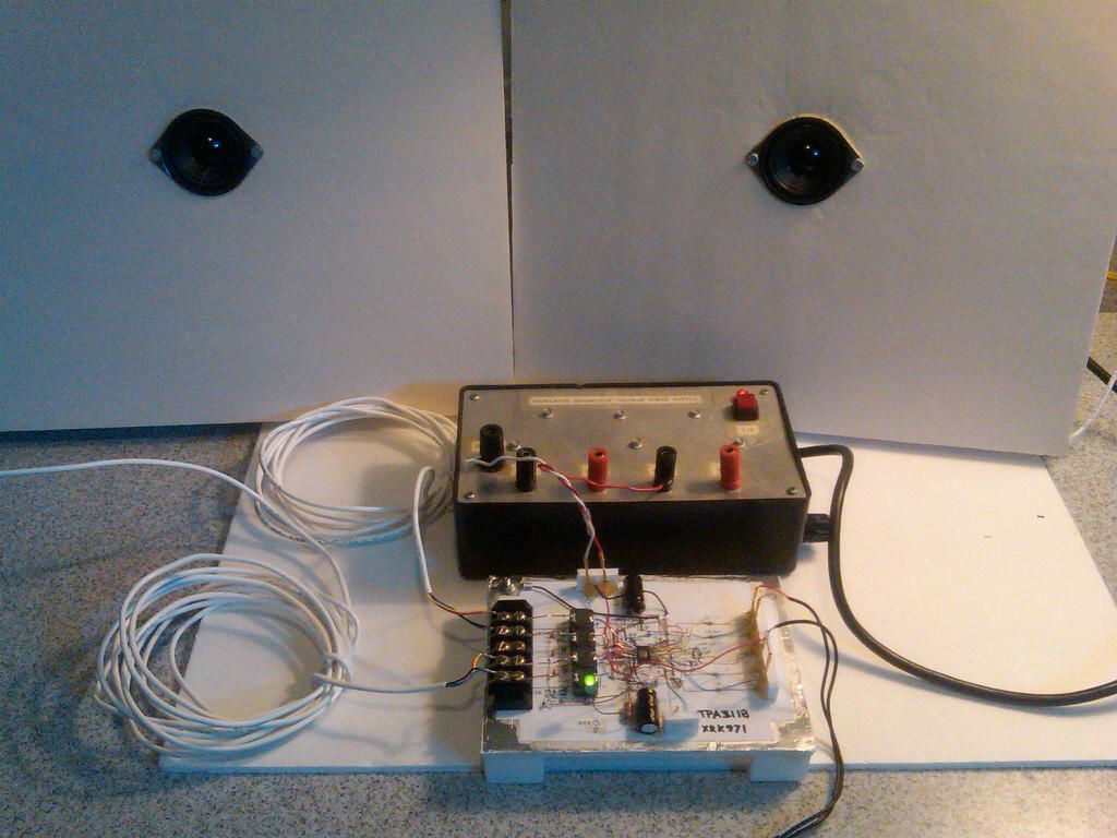
Anyhow, the method works really well. The amps sounds great!
http://www.diyaudio.com/forums/class-d/219730-tpa3118d2-6.html#post3413886
Anyhow, the method works really well. The amps sounds great!
I am wondering what a cheap improvised heat sink may be. It doesn't need to be much as the amp has been running maybe 8 watts without any heatsink. I am thinking a stub of thick 10 gauge copper wire soldered on and soldered to some pennies for the fins.
- Status
- Not open for further replies.
- Home
- Design & Build
- Construction Tips
- Paper and Glue SMD circuit construction